Toyota Venza: Removal
REMOVAL
CAUTION / NOTICE / HINT
NOTICE:
- Do not replace the spiral cable with the battery connected and the ignition switch ON.
- Do not rotate the spiral cable without the steering wheel with the battery connected and the ignition switch ON.
- Ensure that the steering wheel is installed and aligned straight when inspecting the steering sensor.
PROCEDURE
1. TURN FRONT WHEELS TO FACE STRAIGHT AHEAD
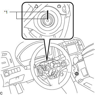
2. REMOVE STEERING PAD
(See page .gif) )
)
3. REMOVE STEERING WHEEL ASSEMBLY
|
(a) Remove the steering wheel assembly set nut. Text in Illustration
|
|
(b) Put matchmarks on the steering wheel assembly and the steering main shaft.
(c) Disconnect each connector from the spiral cable sub-assembly.
|
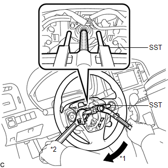
(d) Using SST, remove the steering wheel assembly. Text in Illustration
SST: 09950-50013 09951-05010 09952-05010 09953-05020 09954-05070 NOTICE:
|
|
4. REMOVE STEERING PAD SWITCH ASSEMBLY
|
(a) Remove the 2 screws. Text in Illustration
|
|
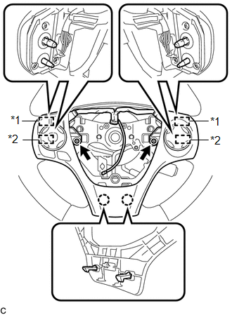
(b) Disengage the 2 claws, 2 pins and 2 guides to remove the steering pad switch assembly.
5. REMOVE CRUISE CONTROL MAIN SWITCH
6. REMOVE CRUISE CONTROL SWITCH WIRE
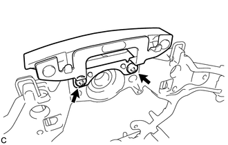
7. REMOVE STEERING SHAKE DAMPER
|
(a) Remove the 2 screws and steering shake damper from the steering wheel sub-assembly. |
|
 Inspection
INSPECTION
PROCEDURE
1. INSPECT STEERING PAD SWITCH ASSEMBLY
(a) Measure the resistance according to the value(s) in the table below.
Standard Resistance:
Tester Connection
...
 Installation
INSTALLATION
CAUTION / NOTICE / HINT
NOTICE:
Do not replace the spiral cable with the battery connected and the ignition
switch ON.
Do not rotate the spiral cable without the steeri ...
Other materials about Toyota Venza:
Installation
INSTALLATION
PROCEDURE
1. INSTALL RADIO AND DISPLAY RECEIVER ASSEMBLY
2. INSTALL NO. 2 RADIO RECEIVER BRACKET
(a) Install the No. 2 radio receiver bracket with the 4 screws.
Torque:
5.0 N·m {51 kgf·cm, 44 in·lbf}
3. INSTALL NO. 1 RADIO RECEIVER BRAC ...
How To Proceed With Troubleshooting
CAUTION / NOTICE / HINT
HINT:
Use the following procedure to troubleshoot the rear view monitor system.
*: Use the Techstream.
PROCEDURE
1.
VEHICLE BROUGHT TO WORKSHOP
NEXT
...
Rear Occupant Classification Sensor RH Circuit Malfunction (B1783)
DESCRIPTION
The rear occupant classification sensor RH circuit consists of the occupant classification
ECU and rear occupant classification sensor RH.
DTC B1783 is recorded when a malfunction is detected in the rear occupant classification
sensor RH circ ...

0.1489