Toyota Venza: Removal
REMOVAL
CAUTION / NOTICE / HINT
CAUTION:
Some of these service operations affect the SRS airbag system. Read the precautionary
notices concerning the SRS airbag system before servicing the steering column (See
page .gif) ).
).
PROCEDURE
1. PRECAUTION
HINT:
(See page )
2. TURN FRONT WHEELS TO FACE STRAIGHT AHEAD
3. REMOVE FRONT WHEEL LH
4. REMOVE STEERING PAD
(See page )
5. REMOVE STEERING WHEEL ASSEMBLY
6. REMOVE DRIVER SIDE KNEE AIRBAG ASSEMBLY
(See page )
7. REMOVE LOWER STEERING COLUMN COVER
|
(a) Remove the 2 screws. |
|
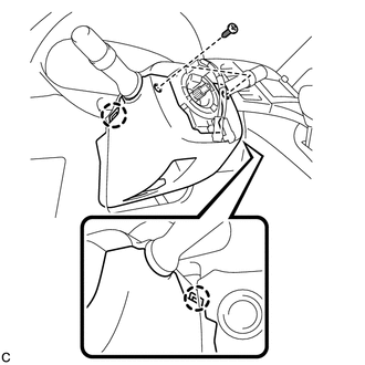
(b) Push the right and left sides of the lower steering column cover, and disengage the 2 claws to remove the lower steering column cover.
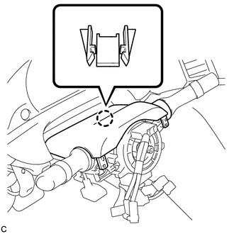
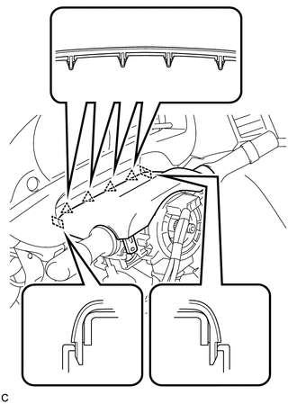
8. REMOVE UPPER STEERING COLUMN COVER
|
(a) Disengage the claw. |
|
|
(b) Disengage the 4 clips and 2 guides to remove the upper steering column cover. |
|
9. REMOVE TURN SIGNAL SWITCH ASSEMBLY WITH SPIRAL CABLE SUB-ASSEMBLY
(a) Disconnect the connectors from the turn signal switch assembly with spiral cable sub-assembly.
|
(b) Using pliers, expand the clamp. Text in Illustration
|
|
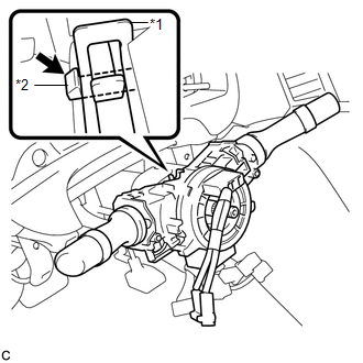
(c) While holding the clamp expanded, raise the claw using a screwdriver to disengage it, and then remove the turn signal switch assembly with spiral cable sub-assembly from the steering column assembly.
NOTICE:
- Do not replace the spiral cable with the battery connected and the ignition switch on.
- Do not rotate the spiral cable without the steering wheel with the battery connected and the ignition switch on.
- Ensure that the steering wheel is installed and aligned straight when inspecting the steering sensor.
- Do not remove the steering sensor from the spiral cable.
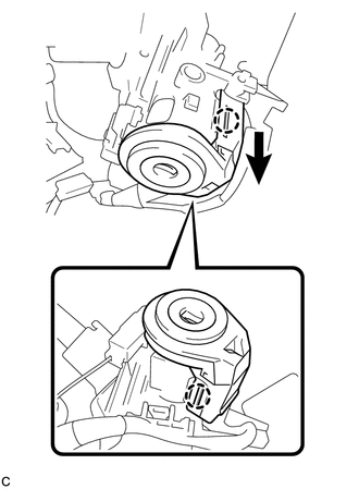
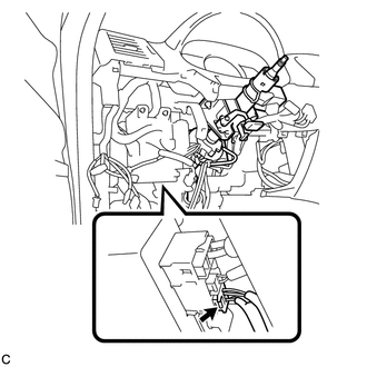
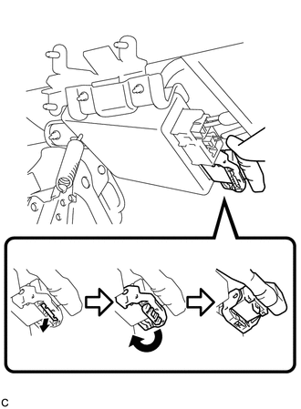
10. REMOVE TRANSPONDER KEY AMPLIFIER (w/o Smart Key System)
|
(a) Slide the transponder key amplifier to disengage the 2 claws as shown in the illustration. |
|
|
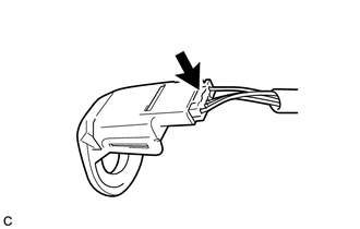
(b) Disconnect the connector and remove the transponder key amplifier. |
|
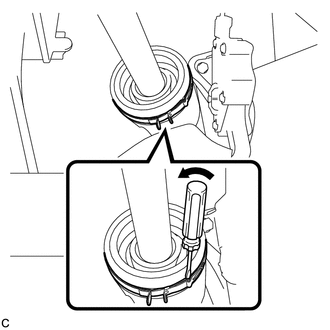
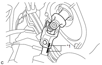
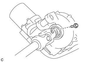
11. SEPARATE STEERING INTERMEDIATE SHAFT ASSEMBLY
|
(a) Using a screwdriver, loosen the clamp. |
|
|
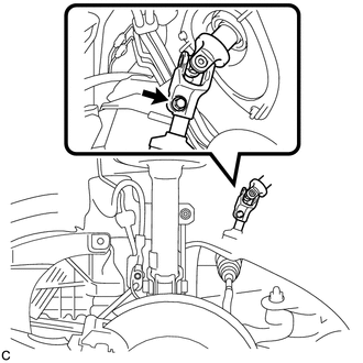
(b) Remove the bolt. NOTICE: Do not separate the steering intermediate shaft assembly from the power steering link assembly. |
|
|
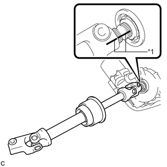
(c) Put matchmarks on the steering intermediate shaft assembly and the power steering link assembly. Text in Illustration
|
|
(d) Separate the steering intermediate shaft assembly from the power steering link assembly.
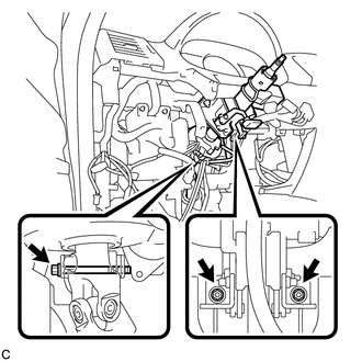
12. REMOVE STEERING POST ASSEMBLY
|
(a) Disconnect the connector from the power steering ECU assembly. |
|
|
(b) Disconnect the connector from the power steering ECU assembly. HINT: Pull out the lock of the lock lever, disengage the claw, and raise the lock lever to disconnect the connector as shown in the illustration. |
|
(c) Disconnect the connectors and disengage the wire harness clamps from the steering post assembly.
|
(d) Remove the bolt, 2 nuts, and the steering post assembly. |
|
13. REMOVE STEERING INTERMEDIATE SHAFT ASSEMBLY
|
(a) Remove the bolt and slide the steering intermediate shaft assembly. NOTICE: Do not separate the steering intermediate shaft assembly from the steering column assembly. |
|
|
(b) Put matchmarks on the steering intermediate shaft assembly and the steering column assembly. Text in Illustration
|
|
(c) Remove the steering intermediate shaft assembly from the steering column assembly.
 Components
COMPONENTS
ILLUSTRATION
ILLUSTRATION
ILLUSTRATION
ILLUSTRATION
ILLUSTRATION
...
 Disassembly
DISASSEMBLY
CAUTION / NOTICE / HINT
NOTICE:
When using a vise, do not overtighten it.
PROCEDURE
1. REMOVE STEERING LOCK ACTUATOR ASSEMBLY (w/ Smart Key System)
(a) Secure the steering column ass ...
Other materials about Toyota Venza:
Front Sensor Communication Malfunction (C1AEC)
DESCRIPTION
This DTC is stored when there is an open or short circuit in the communication
line between the front sensors and the ECU, or when there is a malfunction in a
front sensor.
DTC No.
DTC Detection Condition
Trou ...
Heated Oxygen Sensor
Components
COMPONENTS
ILLUSTRATION
Removal
REMOVAL
PROCEDURE
1. REMOVE NO. 1 ENGINE UNDER COVER
2. REMOVE NO. 2 ENGINE UNDER COVER
3. REMOVE FRONT EXHAUST PIPE ASSEMBLY
4. REMOVE HEATED OXYGEN SENSOR
(a) Using SST, remove the heat ...
Engine Hood Courtesy Switch Circuit
DESCRIPTION
The security courtesy switch is installed together with the hood lock. This switch
turns off when the engine hood is opened and turns on when the engine hood is closed.
WIRING DIAGRAM
PROCEDURE
1.
INSPECT HOOD LOCK AS ...

0.1151