Toyota Venza: Removal
REMOVAL
CAUTION / NOTICE / HINT
CAUTION:
Some of these service operations affect the SRS airbag system. Read the precautionary
notices concerning the SRS airbag system before servicing (See page
.gif) ).
).
NOTICE:
Be sure to read "Precaution" thoroughly before servicing (See page
).
PROCEDURE
1. PLACE FRONT WHEELS FACING STRAIGHT AHEAD
2. DISCONNECT CABLE FROM NEGATIVE BATTERY TERMINAL
CAUTION:
Wait at least 90 seconds after disconnecting the cable from the negative (-) battery terminal to disable the SRS system.
NOTICE:
When disconnecting the cable, some systems need to be initialized after the cable
is reconnected (See page ).
3. REMOVE DRIVER SIDE KNEE AIRBAG ASSEMBLY
HINT:
Refer to the instructions for Removal of the knee airbag assembly (See page
).
4. REMOVE DRIVER SIDE JUNCTION BLOCK ASSEMBLY
(a) Separate the wire harness clamp from the driver side junction block assembly.
(b) Disconnect the connectors from the driver side junction block assembly.
|
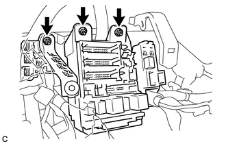
(c) Remove the 3 nuts. |
|
(d) Disconnect the connectors from the back of the driver side junction block assembly.
|
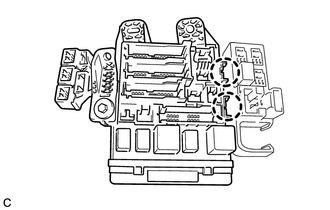
(e) Disengage the 2 claws to remove the driver side junction block assembly. |
|
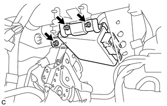
5. REMOVE POWER STEERING ECU ASSEMBLY
|
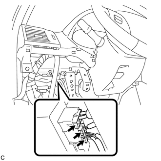
(a) Disconnect the 3 connectors from the power steering ECU assembly. |
|
|
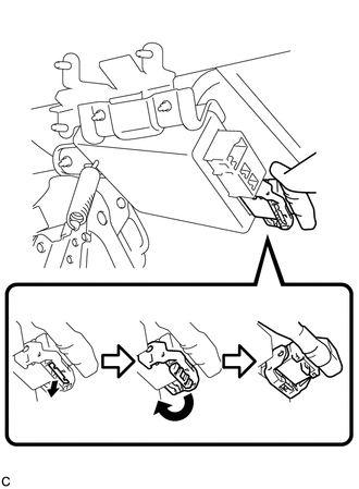
(b) Disconnect the connector from the power steering ECU assembly. HINT: Pull out the lock of the lock lever, disengage the claw, and raise the lock lever to disconnect the connector as shown in the illustration. |
|
|
(c) Remove the 3 nuts and power steering ECU assembly. |
|
|
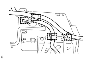
(d) Disengage the 4 wire harness clamps from the power steering ECU assembly |
|
 Components
COMPONENTS
ILLUSTRATION
ILLUSTRATION
...
 Installation
INSTALLATION
PROCEDURE
1. INSTALL POWER STEERING ECU ASSEMBLY
(a) Engage the 4 wire harness clamps to the power steering ECU assembly.
...
Other materials about Toyota Venza:
Diagnostic Trouble Code Chart
DIAGNOSTIC TROUBLE CODE CHART
Lighting System
DTC Code
Detection Item
See page
B1244
Light Sensor Circuit Malfunction
B124D
Lost Communication with AFS LIN
...
Components
COMPONENTS
ILLUSTRATION
ILLUSTRATION
ILLUSTRATION
ILLUSTRATION
ILLUSTRATION
ILLUSTRATION
ILLUSTRATION
ILLUSTRATION
ILLUSTRATION
ILLUSTRATION
ILLUSTRATION
...
Removal
REMOVAL
CAUTION / NOTICE / HINT
HINT:
Use the same procedure for the RH side and LH side.
The procedure listed below is for the LH side.
PROCEDURE
1. REMOVE REAR WHEEL
2. SEPARATE REAR SPEED SENSOR
(a) Remove the bolt and se ...

0.1319