Toyota Venza: Removal
REMOVAL
PROCEDURE
1. DISCONNECT CABLE FROM NEGATIVE BATTERY TERMINAL
NOTICE:
When disconnecting the cable, some systems need to be initialized after the cable
is reconnected (See page .gif) ).
).
2. REMOVE COOL AIR INTAKE DUCT SEAL
3. REMOVE NO. 1 ENGINE COVER SUB-ASSEMBLY
4. REMOVE V-RIBBED BELT
HINT:
See page
5. REMOVE WIRE HARNESS CLAMP BRACKET
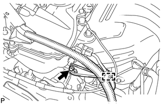
(a) Detach the wire harness clamp from the clamp bracket.
(b) Remove the bolt and clamp bracket.
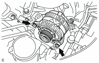
6. REMOVE GENERATOR ASSEMBLY
|
(a) Disconnect the generator connector. |
|
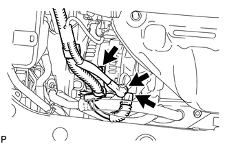
(b) Remove the terminal cap.
(c) Remove the nut and disconnect the generator wire.
(d) Remove the bolt and wire harness clamp bracket.
|
(e) Remove the 2 bolts and generator. |
|
 Components
COMPONENTS
ILLUSTRATION
ILLUSTRATION
ILLUSTRATION
...
 Disassembly
DISASSEMBLY
PROCEDURE
1. REMOVE GENERATOR PULLEY CAP
(a) Using a screwdriver, puncture the center of the generator pulley
cap and pry it off.
NOTICE:
Do not reuse the generator ...
Other materials about Toyota Venza:
Brake Switch "B" Circuit High (P0724)
DESCRIPTION
The purpose of this circuit is to prevent the engine from stalling when brakes
are suddenly applied while driving in lock-up condition.
When the brake pedal is depressed, the stop light switch sends a signal to the
ECM. Then the ECM cancels t ...
Terminals Of Ecu
TERMINALS OF ECU
1. CHECK MAIN BODY ECU (DRIVER SIDE JUNCTION BLOCK ASSEMBLY)
(a) Disconnect the 2C, 2F and 2K main body ECU (driver side junction block assembly)
connectors.
(b) Measure the voltage and resistance according to the value(s) in the table ...
Precaution
PRECAUTION
1. WHEN DISCONNECTING CABLE FROM NEGATIVE BATTERY TERMINAL
NOTICE:
When disconnecting the cable from the negative (-) battery terminal, initialize
the following systems after the cable is reconnected.
System Name
See Proc ...

0.1345