Toyota Venza: Removal
REMOVAL
PROCEDURE
1. DISCHARGE FUEL SYSTEM PRESSURE
HINT:
See page .gif)
2. DISCONNECT CABLE FROM NEGATIVE BATTERY TERMINAL
NOTICE:
When disconnecting the cable, some systems need to be initialized after the cable
is reconnected (See page ).
3. REMOVE WINDSHIELD WIPER MOTOR AND LINK ASSEMBLY
(a) Remove the windshield wiper motor and link assembly (See page
).
4. REMOVE OUTER COWL TOP PANEL
5. REMOVE NO. 1 ENGINE COVER SUB-ASSEMBLY
6. REMOVE NO. 1 VACUUM SWITCHING VALVE ASSEMBLY
7. REMOVE AIR CLEANER CAP SUB-ASSEMBLY
8. REMOVE FUEL TUBE SUB-ASSEMBLY
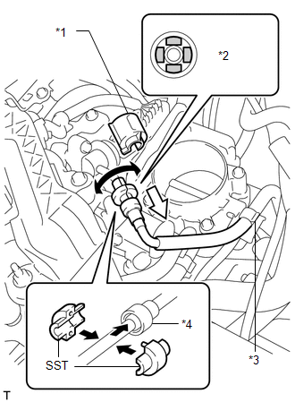 Text in Illustration
|
*1 |
No. 2 Fuel Pipe Clamp |
|
*2 |
Retainer |
|
*3 |
Fuel Hose Clamp |
|
*4 |
Fuel Tube Connector |
.png) |
Turn |
.png) |
Pull |
NOTICE:
Do not forcibly bend, kink or twist the fuel tube.
(a) Remove the No. 2 fuel pipe clamp.
(b) Wipe off any dirt on the fuel tube connector.
(c) Hold the fuel tube connector, and then install SST.
SST: 09268-21011
(d) Turn SST to align the retainer inside the fuel tube connector with the chamfered part of SST.
(e) Insert SST into the fuel tube and hold it. Then push the fuel tube connector toward SST.
(f) Mount the retainer of the fuel tube connector onto the chamfered part of SST.
|
(g) Slide SST and the fuel tube connector together toward the fuel tube until they make a "click" sound, and then disconnect the fuel tube. Text in Illustration
NOTICE:
|
|
(h) Remove the No. 1 fuel pipe clamp.
(i) Pinch the tube connector, and then pull the tube connector off of the pipe.
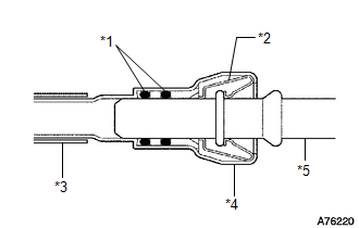
.png) Text in Illustration
Text in Illustration
|
*1 |
Fuel Pipe |
|
*2 |
Fuel Tube Connector |
|
*3 |
Nylon Tube |
|
*4 |
O-ring |
|
*5 |
Retainer |
|
|
Pinch |
|
|
Pull |
NOTICE:
- Check for foreign matter on the fuel tube around the fuel tube connector. Clean it if necessary. Foreign matter can affect the ability of the O-ring to seal the fuel tube connector and fuel pipe.
- Do not use any tools to separate the fuel tube connector and fuel pipe.
- Do not forcibly bend, kink or twist the nylon tube.
- Keep the connector and pipe free from foreign matter.
- If the fuel tube connector and fuel pipe are stuck, push and pull to release them.
- Put the fuel tube connector and fuel pipe in plastic bags to prevent damage and contamination.
(j) Remove the fuel tube sub-assembly from the fuel hose clamp.
9. REMOVE FUEL PRESSURE PULSATION DAMPER ASSEMBLY
|
(a) Remove the 2 bolts and fuel pressure pulsation damper assembly. |
|
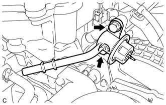
(b) Remove the O-ring from the fuel pressure pulsation damper assembly.
 Components
COMPONENTS
ILLUSTRATION
ILLUSTRATION
ILLUSTRATION
...
 Installation
INSTALLATION
PROCEDURE
1. INSTALL FUEL PRESSURE PULSATION DAMPER ASSEMBLY
(a) Apply a light coat of gasoline or spindle oil to a new O-ring.
Text in Illustration
* ...
Other materials about Toyota Venza:
Cellular Phone Registration Failure
PROCEDURE
1.
CHECK USAGE CONDITION
(a) Check that the vehicle and cellular phone meet the following conditions:
NOTICE:
If changing cellular phone settings, updating software, etc. is necessary, make
sure to obtain the per ...
Steering Pad Switch Circuit
DESCRIPTION
This circuit sends an operation signal from the steering pad switch assembly
to the navigation receiver assembly.
If there is an open in the circuit, the audio system cannot be operated using
the steering pad switch assembly.
If there is a s ...
On-vehicle Inspection
ON-VEHICLE INSPECTION
PROCEDURE
1. INSPECT DRIVER SIDE SEAT BELT WARNING
(a) Turn the ignition switch to ON.
(b) When the driver side seat belt is not fastened, check that the driver side
seat belt warning light on the combination meter assembly blinks.
...

0.1591