Toyota Venza: Removal
REMOVAL
PROCEDURE
1. REMOVE ENGINE OIL LEVEL DIPSTICK GUIDE
|
(a) Remove the engine oil level dipstick. |
|
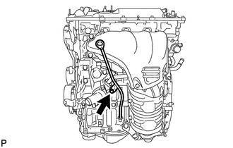
(b) Remove the bolt and engine oil level dipstick guide.
(c) Remove the O-ring from the engine oil level dipstick guide.
2. REMOVE NO. 1 EXHAUST MANIFOLD HEAT INSULATOR
.gif)
3. REMOVE MANIFOLD STAY
4. REMOVE NO. 2 MANIFOLD STAY
5. REMOVE EXHAUST MANIFOLD CONVERTER SUB-ASSEMBLY
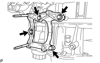
6. REMOVE NO. 1 COMPRESSOR MOUNTING BRACKET
|
(a) Remove the 4 bolts and bracket. |
|
7. REMOVE THROTTLE BODY ASSEMBLY
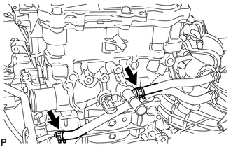
8. REMOVE WATER BY-PASS HOSE
|
(a) Remove the No. 1 and No. 2 water by-pass hoses. |
|
9. DISCONNECT NO. 2 VENTILATION HOSE
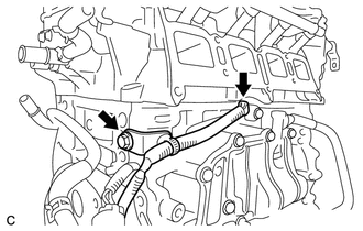
10. REMOVE INTAKE MANIFOLD
11. REMOVE SENSOR WIRE
|
(a) Disconnect the knock control sensor connector. |
|
(b) Remove the bolt and sensor wire.
12. REMOVE KNOCK CONTROL SENSOR
13. REMOVE ENGINE OIL PRESSURE SWITCH ASSEMBLY
14. REMOVE ENGINE COOLANT TEMPERATURE SENSOR
15. REMOVE FUEL DELIVERY PIPE SUB-ASSEMBLY
16. REMOVE IGNITION COIL ASSEMBLY
 Components
COMPONENTS
ILLUSTRATION
ILLUSTRATION
ILLUSTRATION
ILLUSTRATION
ILLUSTRATION
ILLUSTRATION
ILLUSTRATION
ILLUSTRATION
ILLUSTRATION
ILLUSTRATION
...
 Disassembly
DISASSEMBLY
PROCEDURE
1. REMOVE ENGINE COVER JOINT
(a) Remove the 3 joints.
2. REMOVE SPARK PLUG
3. REMOVE CAMSHAFT TIMING OIL CONTROL ...
Other materials about Toyota Venza:
Side Turn Signal Light Assembly
Components
COMPONENTS
ILLUSTRATION
Removal
REMOVAL
CAUTION / NOTICE / HINT
HINT:
Use the same procedure for the RH and LH sides.
The procedure described below is for the LH side.
PROCEDURE
1. REMOVE OUTER MIRROR
2. REMOVE O ...
Disassembly
DISASSEMBLY
PROCEDURE
1. REMOVE BREATHER PLUG HOSE
(a) Using a screwdriver, remove the No. 2 breather plug (ATM) from the
transaxle case sub-assembly.
(b) Using a screwdriver, remove ...
Terminals Of Ecu
TERMINALS OF ECU
1. CHECK POSITION CONTROL ECU AND SWITCH ASSEMBLY
(a) Disconnect the T10 and T11 position control ECU and switch assembly connectors.
(b) Measure the voltage and resistance according to the value(s) in the table
below.
HINT:
Measure t ...

0.1701