Toyota Venza: Reassembly
REASSEMBLY
PROCEDURE
1. INSTALL SHIFT SOLENOID VALVE SL4
|
(a) Coat the shift solenoid valve SL4 and bolt with ATF. Text in Illustration
|
|
.png)
(b) Install the shift solenoid valve SL4 and lock plate to the valve body assembly with the bolt.
Torque:
11 N·m {112 kgf·cm, 8 ft·lbf}
2. INSTALL SHIFT SOLENOID VALVE SL3
|
(a) Coat the shift solenoid valve SL3 and bolt with ATF. Text in Illustration
|
|
.png)
(b) Install the shift solenoid valve SL3 and lock plate to the valve body assembly with the bolt.
Torque:
11 N·m {112 kgf·cm, 8 ft·lbf}
3. INSTALL SHIFT SOLENOID VALVE SL1
|
(a) Coat the shift solenoid valve SL1 with ATF. Text in Illustration
|
|
.png)
(b) Install the shift solenoid valve SL1 to the valve body assembly.
4. INSTALL SHIFT SOLENOID VALVE SL2
(a) Coat the shift solenoid valve SL2 and bolt with ATF.
(b) Install the shift solenoid valve SL2 and lock plate to the valve body assembly with the bolt.
Torque:
11 N·m {112 kgf·cm, 8 ft·lbf}
5. INSTALL SHIFT SOLENOID VALVE SLU
|
(a) Coat the shift solenoid valve SLU with ATF. Text in Illustration
|
|
.png)
(b) Install the shift solenoid valve SLU to the valve body assembly.
6. INSTALL SHIFT SOLENOID VALVE SLT
(a) Coat the shift solenoid valve SLT with ATF.
(b) Install the shift solenoid valve SLT and lock plate to the valve body assembly.
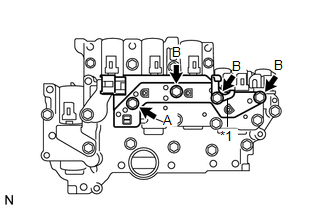
7. INSTALL SHIFT SOLENOID VALVE SL
|
(a) Coat the shift solenoid valve SL with ATF. |
|
.png)
(b) Install the shift solenoid valve SL to the valve body assembly.
8. INSTALL ATF TEMPERATURE SENSOR ASSEMBLY
|
(a) Coat a new O-ring with ATF and install it to the ATF temperature sensor assembly. Text in Illustration
|
|
.png)
|
(b) Coat the 4 bolts with ATF. Text in Illustration
|
|
(c) Install the ATF temperature sensor assembly and clamp to the valve body assembly with the 4 bolts.
Torque:
11 N·m {112 kgf·cm, 8 ft·lbf}
Bolt length:
Bolt A
25 mm (0.984 in.)
Bolt B
85 mm (3.35 in.)
9. INSTALL TRANSMISSION WIRE
.gif)
 Inspection
INSPECTION
PROCEDURE
1. INSPECT SHIFT SOLENOID VALVE SL
(a) Measure the resistance according to the value(s) in the table below.
Text in Illustration
*1
...
 Installation
INSTALLATION
PROCEDURE
1. INSTALL MANUAL VALVE
(a) Coat the manual valve with ATF and install it to the transmission
valve body assembly.
...
Other materials about Toyota Venza:
Door Side Airbag Sensor LH Malfunction (B1695/16)
DESCRIPTION
The side collision sensor LH circuit (to determine deployment of the front seat
side airbag assembly LH and curtain shield airbag assembly LH) is composed of the
center airbag sensor assembly, rear airbag sensor LH and side airbag sensor LH.
...
Problem Symptoms Table
PROBLEM SYMPTOMS TABLE
HINT:
Use the table below to help determine the cause of problem symptoms.
If multiple suspected areas are listed, the potential causes of the symptoms
are listed in order of probability in the "Suspected Area" ...
System Diagram
SYSTEM DIAGRAM
Communication Table
Transmitting ECU
Receiving ECU
Signal
Communication Method
Skid control ECU
AWD control ECU
Wheel speed sensor signal
Stop ...

0.1335