Toyota Venza: Reassembly
REASSEMBLY
CAUTION / NOTICE / HINT
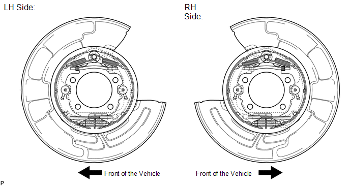
NOTICE:
Before installation, apply high temperature grease to the parts indicated by
arrows (See page .gif) ).
).
PROCEDURE
1. INSTALL NO. 2 PARKING BRAKE SHOE HOLD DOWN SPRING PIN (for 2WD)
|
(a) Install the No. 2 parking brake shoe hold down spring pin. |
|
.png)
2. INSTALL NO. 1 PARKING BRAKE SHOE HOLD DOWN SPRING PIN (for AWD)
|
(a) Install the No. 1 parking brake shoe hold down spring pin. |
|
.png)
3. INSTALL REAR AXLE HUB AND BEARING ASSEMBLY (for 2WD)
NOTICE:
Perform this procedure only when the No. 2 parking brake shoe hold down spring pin is replaced.
HINT:
See page .
4. INSTALL REAR AXLE HUB AND BEARING ASSEMBLY (for AWD)
NOTICE:
Perform this procedure only when the No. 1 parking brake shoe hold down spring pin is replaced.
HINT:
See page .
5. INSTALL NO. 1 PARKING BRAKE SHOE HOLD DOWN SPRING PIN (for 2WD)
|
(a) Install the No. 1 parking brake shoe hold down spring pin. |
|
.png)
6. INSTALL NO. 2 PARKING BRAKE SHOE HOLD DOWN SPRING PIN (for AWD)
|
(a) Install the No. 2 parking brake shoe hold down spring pin. |
|
.png)
7. APPLY HIGH TEMPERATURE GREASE
(a) Apply high temperature grease to the backing plate which makes contact with the shoe.
8. INSTALL PARKING BRAKE SHOE GUIDE PLATE SET BOLT
(a) Apply adhesive to the threads of the parking brake shoe guide plate set bolt.
Adhesive:
Toyota Genuine Adhesive 1344, Three Bond 1344 or equivalent
|
(b) Install the parking brake shoe guide plate and the parking brake shoe guide plate set bolt. Torque: 18 N·m {184 kgf·cm, 13 ft·lbf} |
|
.png)
9. INSTALL PARKING BRAKE SHOE LEVER
(a) Apply high temperature grease to the parking brake shoe lever which makes contact with the No. 2 parking brake shoe assembly.
|
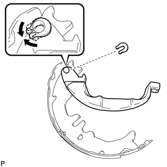
(b) Install the parking brake shoe lever and shim to the No. 2 parking brake shoe assembly with a new C-washer. |
|
|
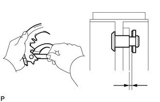
(c) Using a feeler gauge, measure the clearance between the No. 2 parking brake shoe assembly and parking brake shoe lever. Standard clearance: Less than 0.35 mm (0.0138 in.) If the clearance is not as specified, replace the shim with one of the appropriate size.
|
|
10. INSTALL NO. 2 PARKING BRAKE SHOE ASSEMBLY WITH PARKING BRAKE SHOE LEVER
|
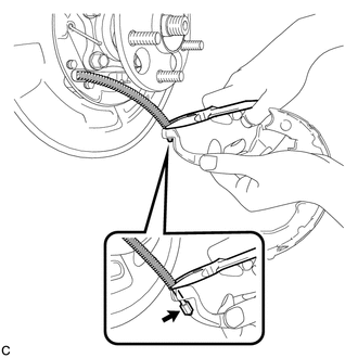
(a) Using needle-nose pliers, connect the No. 3 parking brake cable assembly to the parking brake shoe lever as shown in the illustration. |
|
11. INSTALL NO. 2 PARKING BRAKE SHOE RETURN TENSION SPRING
|
(a) Install the No. 2 parking brake shoe return tension spring to the No. 2 parking brake shoe assembly. |
|
.png)
12. INSTALL NO. 1 PARKING BRAKE SHOE ASSEMBLY
|
(a) Connect the No. 2 parking brake shoe return tension spring to install the No. 1 parking brake shoe assembly. |
|
.png)
13. INSTALL PARKING BRAKE SHOE ADJUSTING SCREW SET
|
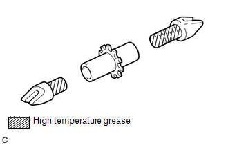
(a) Apply high temperature grease to the parking brake shoe adjusting screw set as shown in the illustration. |
|
|
(b) Install the parking brake shoe adjusting screw set. |
|
.png)
14. INSTALL NO. 2 PARKING BRAKE SHOE ASSEMBLY
|
(a) Install the No. 2 parking brake shoe assembly to the backing plate with the No. 1 parking brake shoe hold down spring cup, parking brake shoe hold down spring and No. 2 parking brake shoe hold down spring cup. |
|
.png)
15. INSTALL PARKING BRAKE SHOE STRUT
|
(a) Install the parking brake shoe strut and the parking brake shoe strut compression spring. |
|
.png)
16. INSTALL NO. 1 PARKING BRAKE SHOE ASSEMBLY
|
(a) Install the No. 1 parking brake shoe assembly to the backing plate with the No. 1 parking brake shoe hold down spring cup, parking brake shoe hold down spring and No. 2 parking brake shoe hold down spring cup. |
|
.png)
17. INSTALL NO. 1 PARKING BRAKE SHOE RETURN TENSION SPRING
|
(a) Install the 2 No. 1 parking brake shoe return tension springs. HINT: First install the front side spring and then the rear side spring. |
|
.png)
18. CHECK PARKING BRAKE INSTALLATION
(a) Check that each part is installed properly.
NOTICE:
There should be no oil or grease on the friction surfaces of the shoe lining and disc.
19. INSTALL REAR DISC
20. INSTALL REAR DISC BRAKE CALIPER ASSEMBLY
|
(a) Install the rear disc brake caliper assembly with the 2 bolts. Torque: 78 N·m {800 kgf·cm, 58 ft·lbf} |
|
.png)
21. INSTALL REAR AXLE SHAFT NUT (for AWD)
NOTICE:
Perform this procedure only when the No. 1 parking brake shoe hold down spring pin is replaced.
HINT:
See page .
22. ADJUST PARKING BRAKE SHOE CLEARANCE
23. INSTALL REAR WHEEL
Torque:
103 N·m {1050 kgf·cm, 76 ft·lbf}
24. BED IN PARKING BRAKE SHOES TO DISCS
(a) Drive the vehicle at about 50 km/h (31 mph) on a safe, level and dry road.
(b) Depress the parking brake pedal with 150 N (15 kgf, 33.7 lbf) of force.
(c) Drive the vehicle for about 400 m (0.25 mile) in this condition.
(d) Repeat this procedure 3 times.
NOTICE:
Set a 5-minute interval between each procedure to prevent the brake assembly from overheating.
25. ADJUST PARKING BRAKE SHOE CLEARANCE AND PARKING BRAKE PEDAL TRAVEL
 Inspection
INSPECTION
PROCEDURE
1. INSPECT BRAKE DISC INSIDE DIAMETER
(a) Using a brake drum gauge or an equivalent tool, measure the inside
diameter of the disc.
Standard inside diameter of ...

Other materials about Toyota Venza:
Components
COMPONENTS
ILLUSTRATION
ILLUSTRATION
ILLUSTRATION
ILLUSTRATION
ILLUSTRATION
ILLUSTRATION
ILLUSTRATION
ILLUSTRATION
ILLUSTRATION
ILLUSTRATION
ILLUSTRATION
ILLUSTRATION
...
Removal
REMOVAL
PROCEDURE
1. REMOVE REAR SEAT HEADREST ASSEMBLY
2. REMOVE REAR SEAT CENTER HEADREST ASSEMBLY
3. REMOVE REAR SEAT INNER TRACK BRACKET COVER
4. REMOVE REAR SEAT OUTER TRACK BRACKET COVER
5. DISCONNECT REAR SEAT RECLINING CONTROL CABLE S ...
Removal
REMOVAL
PROCEDURE
1. DISCONNECT CABLE FROM NEGATIVE BATTERY TERMINAL
NOTICE:
When disconnecting the cable, some systems need to be initialized after the cable
is reconnected (See page ).
2. REMOVE UPPER CONSOLE PANEL SUB-ASSEMBLY (w/o Seat Heater Syste ...

0.1691