Toyota Venza: Reassembly
REASSEMBLY
PROCEDURE
1. INSTALL MAGNETIC CLUTCH ASSEMBLY
|
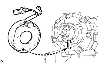
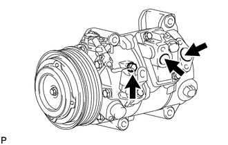
(a) Install the magnetic clutch stator while aligning the protrusion on the stator with the notch on the air compressor assembly as shown in the illustration. |
|
|
(b) Engage the clamp. |
|
.png)
(c) Install the bracket with the screw.
(d) Connect the connector.
|
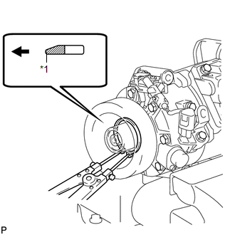
(e) Using a snap ring expander, install a new snap ring with the chamfered side facing up. Text in Illustration
NOTICE: Take care not to damage the seal cover of the bearing when installing the snap ring. |
|
|
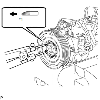
(f) Using a snap ring expander, install the magnetic clutch rotor and a new snap ring with the chamfered side facing up. Text in Illustration
NOTICE:
|
|
(g) Install the magnetic clutch washers and magnetic clutch hub.
NOTICE:
Do not change the combination of the magnetic clutch washers used before disassembly.
|
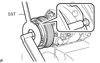
(h) Using SST, hold the magnetic clutch hub and install the bolt. SST: 09985-00270 Torque: 18 N·m {184 kgf·cm, 13 ft·lbf} NOTICE: Make sure that there is no foreign matter or oil on the compressor shaft, bolt and clutch hub. |
|
2. INSPECT MAGNETIC CLUTCH CLEARANCE
|
(a) Set the dial indicator to the magnetic clutch hub. |
|
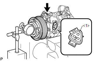
(b) Connect a positive (+) lead from the battery to terminal 1 of the magnetic clutch connector, and a negative (-) lead to the ground wire. Turn the magnetic clutch on and off and measure the clearance.
Standard clearance:
0.26 to 0.60 mm (0.0103 to 0.0236 in.)
If the measured value is not within the standard range, remove the magnetic clutch hub and adjust it with magnetic clutch washers.
NOTICE:
Adjustment should be performed with 3 or less magnetic clutch washers.
(c) Remove the compressor and magnetic clutch from the vise.
3. ADJUST COMPRESSOR OIL LEVEL
|
(a) When replacing the compressor and magnetic clutch with a new one, gradually discharge the refrigerant from the service valve, and drain the following amount of oil from the new compressor and magnetic clutch before installation. Standard: (Oil capacity inside the new compressor and magnetic clutch: 130 + 15 cc (4.4 + 0.51 fl.oz.) ) - (Remaining oil amount in the removed compressor and magnetic clutch) = (Oil amount to be removed from the new compressor when replacing) NOTICE:
|
|
 Installation
INSTALLATION
PROCEDURE
1. TEMPORARILY TIGHTEN COMPRESSOR AND MAGNETIC CLUTCH
(a) Temporarily install the compressor and magnetic clutch and bracket
with the 4 bolts.
...
 Condenser
...
Other materials about Toyota Venza:
Data Signal Circuit between Navigation Receiver Assembly and Stereo Jack Adapter
DESCRIPTION
The No. 1 stereo jack adapter assembly sends the sound data signal or image data
signal from a USB device to the navigation receiver assembly via this circuit.
WIRING DIAGRAM
PROCEDURE
1.
CHECK HARNESS AND CONNECTOR ( ...
Adjustment
ADJUSTMENT
CAUTION / NOTICE / HINT
CAUTION:
Before adjusting the door positions of vehicles equipped with side and curtain
shield airbags, be sure to disconnect the battery. After adjustment, check that
the SRS warning light is operating normally and ...
Power Mirrors do not Return to Memorized Position
SYSTEM DESCRIPTION
If either the M1 or M2 seat memory switch is pressed, the outer mirror control
ECU assembly (driver door) detects the seat memory switch status and sends the switch
signal to the main body ECU (driver side junction block assembly) via C ...

0.1409