Toyota Venza: Reassembly
REASSEMBLY
PROCEDURE
1. INSTALL GENERATOR ROTOR ASSEMBLY
(a) Place the drive end frame on the clutch pulley.
|
(b) Install the generator rotor assembly to the drive end frame. |
|
.png)
2. INSTALL GENERATOR CLUTCH PULLEY
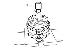
(a) Temporarily install the clutch pulley onto the rotor shaft.
(b) Mount the generator drive end frame in a vise tightly.
|
(c) Confirm SST (A) and (B) shown in the illustration. Text in Illustration
SST: 09820-63021 |
|
.png)
|
(d) Place the rotor shaft end into SST (A). Text in Illustration
|
|
.png)
|
(e) Fit SST (B) to the clutch pulley. Text in Illustration
|
|
.png)
|
(f) Tighten the pulley by turning SST (B) in the direction shown in the illustration. Text in Illustration
Torque: without SST : 80 N·m {816 kgf·cm, 59 ft·lbf} with SST : 64 N·m {653 kgf·cm, 47 ft·lbf} NOTICE:
|
|
(g) Remove SST from the generator assembly.
(h) Check that the clutch pulley rotates smoothly.
(i) Install a new clutch pulley cap to the clutch pulley.
3. INSTALL GENERATOR COIL ASSEMBLY
|
(a) Place a new generator washer on the generator rotor. |
|
.png)
|
(b) Using a deep socket wrench (21 mm) and a press, slowly press in the generator coil assembly. Text in Illustration
|
|
|
(c) Install the 4 bolts. Torque: 5.9 N·m {60 kgf·cm, 52 in·lbf} |
|
.png)
4. INSTALL GENERATOR BRUSH HOLDER ASSEMBLY
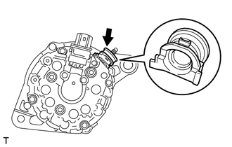
|
(a) While pushing the 2 brushes into the generator brush holder assembly, insert a 1.0 mm (0.0394 in.) pin into the brush holder hole. Text in Illustration
|
|
.png)
|
(b) Install the brush holder assembly to the generator coil with the 2 screws. Torque: 1.8 N·m {18 kgf·cm, 16 in·lbf} |
|

(c) Pull out the pin from the generator brush holder.
Text in Illustration|
*1 |
Pin |
5. INSTALL TERMINAL INSULATOR
|
(a) Install the terminal insulator to the generator coil. NOTICE: Be sure to install the terminal insulator in the correct direction. |
|
6. INSTALL GENERATOR REAR END COVER
|
(a) Install the generator rear end cover to the generator coil with the 3 nuts. Torque: 4.6 N·m {47 kgf·cm, 41 in·lbf} |
|
.png)
 Installation
INSTALLATION
PROCEDURE
1. INSTALL GENERATOR ASSEMBLY
(a) Install the wire harness clamp with the bolt.
Torque:
8.4 N·m {86 kgf·cm, 74 in·lbf}
...
 Networking
...
Other materials about Toyota Venza:
Removal
REMOVAL
PROCEDURE
1. REMOVE AUTOMATIC TRANSAXLE ASSEMBLY
HINT:
See the steps from "Remove Engine Assembly with transaxle" through "Remove Automatic
Transaxle Assembly" (See page ).
2. REMOVE AUTOMATIC TRANSAXLE OIL PAN SUB-ASSEMBLY
...
Inspection
INSPECTION
PROCEDURE
1. INSPECT VACUUM SWITCHING VALVE ASSEMBLY (for ACIS)
(a) Measure the resistance according to the value(s) in the table below.
Text in Illustration
*1
Body Ground
Stan ...
ACIS Control Circuit
DESCRIPTION
This circuit opens and closes the Intake Air Control Valve (IACV) in response
to the engine load in order to increase the intake efficiency (ACIS: Acoustic Control
Induction System).
WIRING DIAGRAM
CAUTION / NOTICE / HINT
NOTICE:
Inspe ...

0.1476