Toyota Venza: Rear Stabilizer Bar(for 2wd)
Components
COMPONENTS
ILLUSTRATION
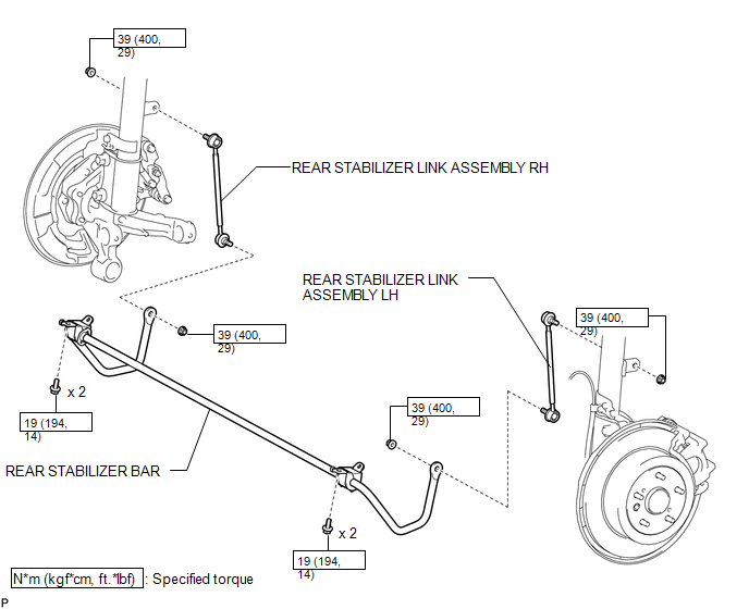
ILLUSTRATION
Removal
REMOVAL
PROCEDURE
1. REMOVE REAR WHEELS
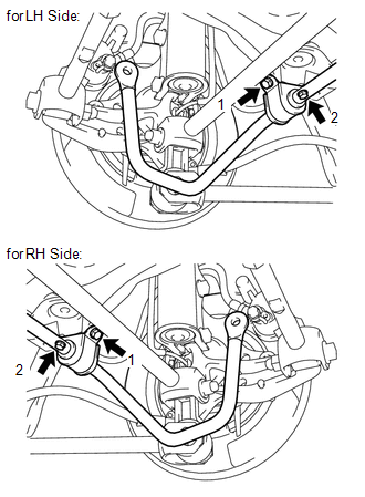
2. REMOVE REAR STABILIZER LINK ASSEMBLY LH
|
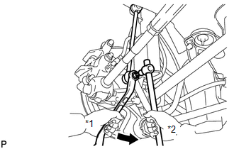
(a) Remove the nut and separate the rear stabilizer link assembly LH from the rear stabilizer bar. Text in Illustration
HINT: If the ball joint turns together with the nut, use a hexagon wrench (5 mm) to hold the stud bolt. |
|
|
(b) Remove the nut and the rear stabilizer link assembly LH from the rear shock absorber with coil spring LH. Text in Illustration
HINT: If the ball joint turns together with the nut, use a hexagon wrench (5 mm) to hold the stud bolt. |
|
3. REMOVE REAR STABILIZER LINK ASSEMBLY RH
HINT:
Perform the same procedure as the LH side.
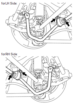
4. REMOVE REAR STABILIZER BAR
|
(a) Remove the 4 bolts and rear stabilizer bar. |
|
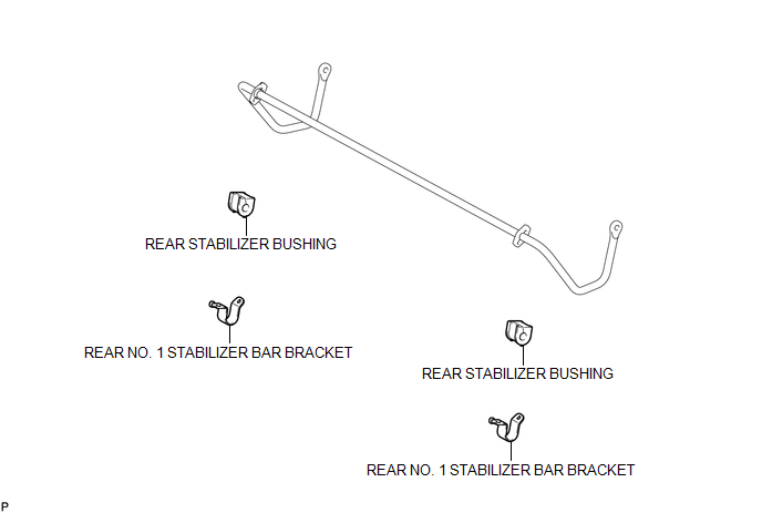
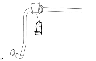
5. REMOVE REAR NO. 1 STABILIZER BAR BRACKET (for LH Side)
|
(a) Remove the rear No. 1 stabilizer bar bracket. |
|
6. REMOVE REAR NO. 1 STABILIZER BAR BRACKET (for RH Side)
HINT:
Perform the same procedure as the LH side.
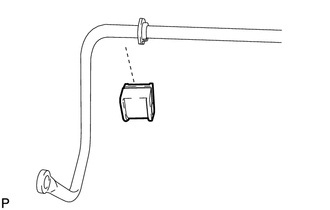
7. REMOVE REAR STABILIZER BUSHING (for LH Side)
|
(a) Remove the rear stabilizer bushing. |
|
8. REMOVE REAR STABILIZER BUSHING (for RH Side)
HINT:
Perform the same procedure as the LH side.
Inspection
INSPECTION
PROCEDURE
1. INSPECT REAR STABILIZER LINK ASSEMBLY
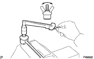
|
(a) As shown in the illustration, move the ball joint stud back and forth 5 times before installing the nut. |
|
(b) Using a torque wrench, turn the nut continuously at a rate of 3 to 5 seconds per turn and take the torque reading on the fifth turn.
Turning torque:
1.0 N*m (10 kgf*cm, 9 in.*lbf) or less
If the turning torque is not within the specified range, replace the rear stabilizer link assembly with a new one.
(c) Check for any cracks and grease leaks on the ball joint dust cover.
(d) Check that neither unusual drag nor rattle occurs during rotation.
Installation
INSTALLATION
PROCEDURE
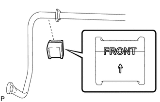
1. INSTALL REAR STABILIZER BUSHING (for LH Side)
|
(a) Install the rear stabilizer bushing. NOTICE: Bushing slit should always face vehicle forwards, even if bushing "FRONT" text does not exist. |
|
2. INSTALL REAR STABILIZER BUSHING (for RH Side)
HINT:
Perform the same procedure as the LH side.
3. INSTALL REAR NO. 1 STABILIZER BAR BRACKET (for LH Side)
|
(a) Install the rear No. 1 stabilizer bar bracket. |
|
4. INSTALL REAR NO. 1 STABILIZER BAR BRACKET (for RH Side)
HINT:
Perform the same procedure as the LH side.
5. INSTALL REAR STABILIZER BAR
|
(a) Install the rear stabilizer bar with the 4 bolts in order 1 to 2. Torque: 19 N·m {194 kgf·cm, 14 ft·lbf} |
|
6. INSTALL REAR STABILIZER LINK ASSEMBLY LH
|
(a) Install the rear stabilizer link assembly LH to the rear shock absorber with coil spring LH with the nut. Text in Illustration
Torque: 39 N·m {400 kgf·cm, 29 ft·lbf} HINT: If the ball joint turns together with the nut, use a hexagon wrench (5 mm) to hold the stud bolt. |
|
|
(b) Install the rear stabilizer link assembly LH to the rear stabilizer bar with the nut. Text in Illustration
Torque: 39 N·m {400 kgf·cm, 29 ft·lbf} HINT: If the ball joint turns together with the nut, use a hexagon wrench (5 mm) to hold the stud bolt. |
|
7. INSTALL REAR STABILIZER LINK ASSEMBLY RH
HINT:
Perform the same procedure as the LH side.
8. INSTALL REAR WHEELS
Torque:
103 N·m {1050 kgf·cm, 76 ft·lbf}
 Disposal
DISPOSAL
PROCEDURE
1. DISPOSE OF REAR SHOCK ABSORBER
(a) Fully extend the shock absorber piston rod.
(b) Using a drill, make a hole in are ...
Other materials about Toyota Venza:
Disabling the TRAC system
If the vehicle gets stuck in mud, dirt or snow, the TRAC system may reduce power
from the engine to the wheels. Pressing
to turn the system off may make it
easier for you to rock the vehicle in order to free it.
To turn the TRAC system off, quickly pr ...
Clearance Warning Buzzer Circuit
DESCRIPTION
This circuit consists of the No. 1 clearance warning buzzer and clearance warning
ECU assembly. An ECU-excited type buzzer is used. The ECU operates the buzzer using
a sound pattern that changes depending on the distance to the obstacle.
WIRI ...
Winter driving tips
Carry out the necessary preparations and inspections before driving the vehicle
in winter. Always drive the vehicle in a manner appropriate to the prevailing weather
conditions.
- Pre-winter preparations
• Use fluids that are appropriate to the p ...
0.1727

.png)
.png)
.png)
.png)
