Toyota Venza: Rear Sensor Communication Malfunction (C1AED)
DESCRIPTION
This DTC is stored when there is an open or short circuit in the communication line between the rear sensors and the ECU, or when there is a malfunction in a rear sensor.
|
DTC No. |
DTC Detection Condition |
Trouble Area |
|---|---|---|
|
C1AED |
An open or short circuit in the communication line between the rear sensors and ECU or a malfunction in a rear sensor during initialization mode after the engine switch is turned on (IG). |
|
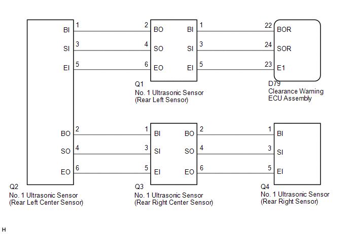
WIRING DIAGRAM
PROCEDURE
|
1. |
CHECK DTC OUTPUT (C1AED) |
(a) Check for DTCs (See page .gif) ).
).
(b) Clear the DTCs (See page ).
(c) Recheck for DTCs (See page ).
|
Result |
Proceed to |
|---|---|
|
DTC C1AED is output |
A |
|
No DTCs are output |
B |
| B | .gif) |
USE SIMULATION METHOD TO CHECK |
|
.gif)
|
2. |
CHECK HARNESS AND CONNECTOR (CLEARANCE WARNING ECU ASSEMBLY - REAR LEFT SENSOR) |
(a) Disconnect the D79 clearance warning ECU assembly connector.
(b) Disconnect the Q1 No. 1 ultrasonic sensor connector.
(c) Measure the resistance according to the value(s) in the table below.
Standard Resistance:
|
Tester Connection |
Condition |
Specified Condition |
|---|---|---|
|
D79-22 (BOR) - Q1-1 (BI) |
Always |
Below 1 Ω |
|
D79-24 (SOR) - Q1-3 (SI) |
Always |
Below 1 Ω |
|
D79-23 (E1) - Q1-5 (EI) |
Always |
Below 1 Ω |
|
D79-22 (BOR) - Body ground |
Always |
10 kΩ or higher |
|
D79-24 (SOR) - Body ground |
Always |
10 kΩ or higher |
|
D79-23 (E1) - Body ground |
Always |
10 kΩ or higher |
| NG | |
REPAIR OR REPLACE HARNESS OR CONNECTOR |
|
|
3. |
CHECK HARNESS AND CONNECTOR (REAR LEFT SENSOR - REAR LEFT CENTER SENSOR) |
(a) Disconnect the Q2 No. 1 ultrasonic sensor connector.
(b) Measure the resistance according to the value(s) in the table below.
Standard Resistance:
|
Tester Connection |
Condition |
Specified Condition |
|---|---|---|
|
Q1-2 (BO) - Q2-1 (BI) |
Always |
Below 1 Ω |
|
Q1-4 (SO) - Q2-3 (SI) |
Always |
Below 1 Ω |
|
Q1-6 (EO) - Q2-5 (EI) |
Always |
Below 1 Ω |
|
Q1-2 (BO) - Body ground |
Always |
10 kΩ or higher |
|
Q1-4 (SO) - Body ground |
Always |
10 kΩ or higher |
|
Q1-6 (EO) - Body ground |
Always |
10 kΩ or higher |
| NG | |
REPAIR OR REPLACE HARNESS OR CONNECTOR |
|
|
4. |
CHECK HARNESS AND CONNECTOR (REAR LEFT CENTER SENSOR - REAR RIGHT CENTER SENSOR) |
(a) Disconnect the Q3 No. 1 ultrasonic sensor connector.
(b) Measure the resistance according to the value(s) in the table below.
Standard Resistance:
|
Tester Connection |
Condition |
Specified Condition |
|---|---|---|
|
Q2-2 (BO) - Q3-1 (BI) |
Always |
Below 1 Ω |
|
Q2-4 (SO) - Q3-3 (SI) |
Always |
Below 1 Ω |
|
Q2-6 (EO) - Q3-5 (EI) |
Always |
Below 1 Ω |
|
Q2-2 (BO) - Body ground |
Always |
10 kΩ or higher |
|
Q2-4 (SO) - Body ground |
Always |
10 kΩ or higher |
|
Q2-6 (EO) - Body ground |
Always |
10 kΩ or higher |
| NG | |
REPAIR OR REPLACE HARNESS OR CONNECTOR |
|
|
5. |
CHECK HARNESS AND CONNECTOR (REAR RIGHT CENTER SENSOR - REAR RIGHT SENSOR) |
(a) Disconnect the Q4 No. 1 ultrasonic sensor connector.
(b) Measure the resistance according to the value(s) in the table below.
Standard Resistance:
|
Tester Connection |
Condition |
Specified Condition |
|---|---|---|
|
Q3-2 (BO) - Q4-1 (BI) |
Always |
Below 1 Ω |
|
Q3-4 (SO) - Q4-3 (SI) |
Always |
Below 1 Ω |
|
Q3-6 (EO) - Q4-5 (EI) |
Always |
Below 1 Ω |
|
Q3-2 (BO) - Body ground |
Always |
10 kΩ or higher |
|
Q3-4 (SO) - Body ground |
Always |
10 kΩ or higher |
|
Q3-6 (EO) - Body ground |
Always |
10 kΩ or higher |
| NG | |
REPAIR OR REPLACE HARNESS OR CONNECTOR |
|
|
6. |
INSPECT NO. 1 ULTRASONIC SENSOR (REAR LEFT SENSOR) |
|
(a) Measure the resistance according to the value(s) in the table below. Standard Resistance:
|
|
.png)
| NG | |
REPLACE NO. 1 ULTRASONIC SENSOR (REAR LEFT SENSOR) |
|
|
7. |
INSPECT NO. 1 ULTRASONIC SENSOR (REAR LEFT CENTER SENSOR) |
|
(a) Measure the resistance according to the value(s) in the table below. Standard Resistance:
|
|
| NG | |
REPLACE NO. 1 ULTRASONIC SENSOR (REAR LEFT CENTER SENSOR) |
|
|
8. |
INSPECT NO. 1 ULTRASONIC SENSOR (REAR RIGHT CENTER SENSOR) |
|
(a) Measure the resistance according to the value(s) in the table below. Standard Resistance:
|
|
| NG | |
REPLACE NO. 1 ULTRASONIC SENSOR (REAR RIGHT CENTER SENSOR) |
|
|
9. |
REPLACE NO. 1 ULTRASONIC SENSOR (REAR LEFT SENSOR) |
|
|
10. |
CHECK DTC OUTPUT (C1AED) |
(a) Clear the DTCs (See page ).
(b) Check for DTCs (See page ).
|
Result |
Proceed to |
|---|---|
|
DTC C1AED is output |
A |
|
No DTCs are output |
B |
| B | |
END |
|
|
11. |
REPLACE NO. 1 ULTRASONIC SENSOR (REAR LEFT CENTER SENSOR) |
|
|
12. |
CHECK DTC OUTPUT (C1AED) |
(a) Clear the DTCs (See page ).
(b) Check for DTCs (See page ).
|
Result |
Proceed to |
|---|---|
|
DTC C1AED is output |
A |
|
No DTCs are output |
B |
| B | |
END |
|
|
13. |
REPLACE NO. 1 ULTRASONIC SENSOR (REAR RIGHT CENTER SENSOR) |
|
|
14. |
CHECK DTC OUTPUT (C1AED) |
(a) Clear the DTCs (See page ).
(b) Check for DTCs (See page ).
|
Result |
Proceed to |
|---|---|
|
DTC C1AED is output |
A |
|
No DTCs are output |
B |
| B | |
END |
|
|
15. |
REPLACE NO. 1 ULTRASONIC SENSOR (REAR RIGHT SENSOR) |
|
|
16. |
CHECK DTC OUTPUT (C1AED) |
(a) Clear the DTCs (See page ).
(b) Check for DTCs (See page ).
|
Result |
Proceed to |
|---|---|
|
DTC C1AED is output |
A |
|
No DTCs are output |
B |
| A | |
REPLACE CLEARANCE WARNING ECU ASSEMBLY |
| B | |
END |
 Front Sensor Communication Malfunction (C1AEC)
DESCRIPTION
This DTC is stored when there is an open or short circuit in the communication
line between the front sensors and the ECU, or when there is a malfunction in a
front sensor.
...
 Rear Right Sensor Malfunction (C1AE9)
DESCRIPTION
The No. 1 ultrasonic sensor (rear right sensor) is installed on the rear bumper.
The ECU detects obstacles based on signals received from the No. 1 ultrasonic sensor
(rear right senso ...
Other materials about Toyota Venza:
Problem Symptoms Table
PROBLEM SYMPTOMS TABLE
HINT:
Use the table below to help determine the cause of problem symptoms.
If multiple suspected areas are listed, the potential causes of the symptoms
are listed in order of probability in the "Suspected Area" ...
Customize Parameters
CUSTOMIZE PARAMETERS
1. CUSTOMIZE LIGHTING SYSTEM (EXT)
HINT:
The following items can be customized.
NOTICE:
When the customer requests a change in a function, first make sure that
the function can be customized.
Be sure to make a note of ...
Portable Player cannot be Connected Manually/Automatically
CAUTION / NOTICE / HINT
HINT:
Some versions of "Bluetooth" compatible audio players may not function properly,
or the functions may be limited using the navigation receiver assembly, even if
the portable audio player itself can play files (See ...

0.142