Toyota Venza: Rear Power Window RH Auto Up / Down Function does not Operate with Rear Power Window Switch RH
DESCRIPTION
If the manual up/down function can be performed but the auto up/down function cannot, the fail-safe mode may be functioning.
If the power window initialization (See page
.gif) ) has not been performed, the auto up/down function
) has not been performed, the auto up/down function
will not operate.
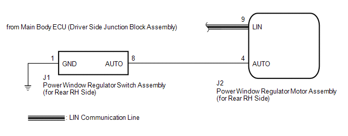
WIRING DIAGRAM
CAUTION / NOTICE / HINT
NOTICE:
- The power window control system uses a multiplex communication system
(LIN communication system). Inspect the communication function by following
How to Proceed with Troubleshooting (See page
). Troubleshoot the power window control
system after confirming that the communication system is functioning properly. - When the power window regulator motor assembly (for rear RH side) is reinstalled or replaced, the power window control system must be initialized.
- After a door glass or a door glass run has been replaced, the jam protection
function may operate unexpectedly when the auto up function is used. In
such cases, the auto up function can be reinitialized by repeating the following
operations at least 5 times:
- Close the power window by fully pulling up the power window regulator switch assembly (for rear RH side) and holding it at the auto up position.
- Open the power window by fully pushing down the power window regulator switch assembly (for rear RH side).
- When the ECU determines that the power window regulator motor assembly (for rear RH side) has a malfunction, DTC B2311 is set.
PROCEDURE
|
1. |
READ VALUE USING TECHSTREAM (RR-Door Motor) |
(a) Connect the Techstream to the DLC3.
(b) Turn the ignition switch to ON.
(c) Turn the Techstream on.
(d) Enter the following menus: Body Electrical / RR-Door Motor / Data List.
(e) Read the Data List according to the display on the Techstream.
RR-Door Motor (Power Window Regulator Motor Assembly (for Rear RH Side))|
Tester Display |
Measurement Item/Range |
Normal Condition |
Diagnostic Note |
|---|---|---|---|
|
RR Door P/W Auto SW |
Rear RH side power window auto switch signal / ON or OFF |
ON: Rear RH power window auto switch operated OFF: Rear RH power window auto switch not operated |
- |
OK:
On the Techstream screen, ON or OFF is displayed accordingly.
| NG | .gif) |
GO TO STEP 4 |
|
.gif)
|
2. |
PERFORM INITIALIZATION (for Rear RH Side) |
(a) Initialize the power window regulator motor assembly (for rear RH side) (See
page ).
|
|
3. |
CHECK POWER WINDOW CONTROL SYSTEM (AUTO UP/DOWN FUNCTION) |
(a) Check that the rear RH side door power window moves when the auto up/down
function of the power window regulator switch assembly (for rear RH side) is operated
(See page ).
OK:
Rear RH side auto up/down function is normal.
| OK | |
END (PROBLEM DUE TO INITIALIZATION FAILURE) |
| NG | |
REPLACE POWER WINDOW REGULATOR MOTOR ASSEMBLY (for Rear RH Side) |
|
4. |
INSPECT POWER WINDOW REGULATOR SWITCH ASSEMBLY (for Rear RH Side) |
|
(a) Remove the power window regulator switch assembly (for rear RH side)
(See page |
|
.png)
(b) Measure the resistance according to the value(s) in the table below.
Standard Resistance:
|
Tester Connection |
Condition |
Specified Condition |
|---|---|---|
|
8 (AUTO) - 1 (GND) |
Auto up or auto down position |
Below 1 Ω |
|
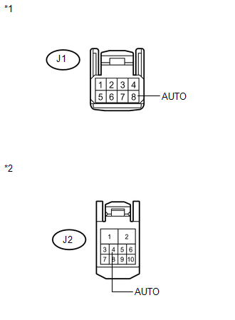
*1 |
Component without harness connected (Power Window Regulator Switch Assembly (for Rear RH Side)) |
| NG | |
REPLACE POWER WINDOW REGULATOR SWITCH ASSEMBLY (for Rear RH Side) |
|
|
5. |
CHECK HARNESS OR CONNECTOR (REAR RH SIDE SWITCH - REAR RH SIDE MOTOR) |
|
(a) Disconnect the power window regulator motor assembly (for rear RH side) connector. |
|
(b) Measure the resistance according to the value(s) in the table below.
Standard Resistance:
|
Tester Connection |
Condition |
Specified Condition |
|---|---|---|
|
J1-8 (AUTO) - J2-4 (AUTO) |
Always |
Below 1 Ω |
|
J1-8 (AUTO) - Body ground |
Always |
10 kΩ or higher |
|
*1 |
Front view of wire harness connector (to Power Window Regulator Switch Assembly (for Rear RH Side)) |
|
*2 |
Front view of wire harness connector (to Power Window Regulator Motor Assembly (for Rear RH Side)) |
| OK | |
REPLACE POWER WINDOW REGULATOR MOTOR ASSEMBLY (for Rear RH Side) |
| NG | |
REPAIR OR REPLACE HARNESS OR CONNECTOR |
 Rear Power Window LH Auto Up / Down Function does not Operate with Rear Power
Window Switch LH
Rear Power Window LH Auto Up / Down Function does not Operate with Rear Power
Window Switch LH
DESCRIPTION
If the manual up/down function can be performed but the auto up/down function
cannot, the fail-safe mode may be functioning.
If the power window initialization (See page
) has not be ...
 Key-off Operation Function Operates even if Operating Conditions are not Satisfied
DESCRIPTION
When the front doors are closed, each power window regulator motor assembly
can control its power window operation for approximately 45 seconds after
the ignition switch is ...
Other materials about Toyota Venza:
Clock Display Circuit
DESCRIPTION
The accessory meter assembly uses this circuit to communicate with the combination
meter assembly via the direct line. The accessory meter assembly uses this circuit
to receive the drive monitor switch signals from the combination meter assemb ...
Noise Occurs from Generator while Engine is Running
PROCEDURE
1.
CHECK LOOSENESS OF V-RIBBED BELT
(a) Check the tension of the belt by pushing it down with a finger.
OK:
The tension of the belt is enough.
NG
REPLACE V-RIBBED BELT TENSIONER ASSEMBLY
...
On-vehicle Inspection
ON-VEHICLE INSPECTION
CAUTION / NOTICE / HINT
CAUTION:
Be sure to follow the correct removal and installation procedures of the rear
airbag sensor.
PROCEDURE
1. INSPECT REAR AIRBAG SENSOR (VEHICLE NOT INVOLVED IN COLLISION)
(a) Perform a diagnostic sys ...

0.1571