Toyota Venza: Power Window Master Switch
Components
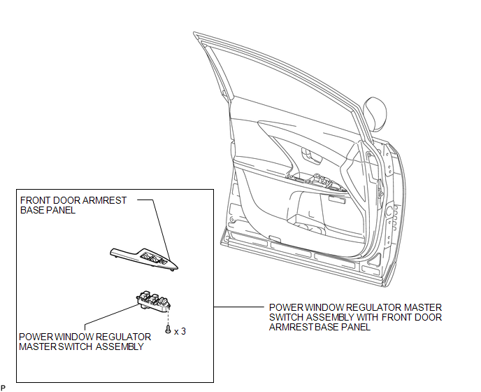
COMPONENTS
ILLUSTRATION
Removal
REMOVAL
PROCEDURE
1. REMOVE POWER WINDOW REGULATOR MASTER SWITCH ASSEMBLY WITH FRONT DOOR ARMREST BASE PANEL
.gif)
2. REMOVE POWER WINDOW REGULATOR MASTER SWITCH ASSEMBLY
|
(a) Remove the 3 screws and the power window regulator master switch assembly. |
|
Inspection
INSPECTION
PROCEDURE
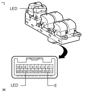
1. INSPECT POWER WINDOW REGULATOR MASTER SWITCH ASSEMBLY
|
(a) Check that the LED illuminates. (1) Apply battery voltage to the power window regulator master switch assembly and check that the LED illuminates. OK:
If the result is not as specified, replace the power window regulator master switch assembly. |
|
Installation
INSTALLATION
PROCEDURE
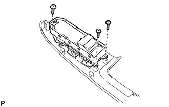
1. INSTALL POWER WINDOW REGULATOR MASTER SWITCH ASSEMBLY
|
(a) Install the power window regulator master switch assembly with the 3 screws. |
|
.png)
2. INSTALL POWER WINDOW REGULATOR MASTER SWITCH ASSEMBLY WITH FRONT DOOR ARMREST BASE PANEL
.gif)
 Jam Protection Function does not Operate
DESCRIPTION
This symptom may occur for any of the windows.
The jam protection function operates within a specified range during the manual
up or auto up operation.
CAUTION / NOTICE / HINT
NOT ...

Other materials about Toyota Venza:
Relay
On-vehicle Inspection
ON-VEHICLE INSPECTION
PROCEDURE
1. INSPECT STARTER RELAY
(a) Measure the resistance according to the value(s) in the table below.
Standard Resistance:
Tester Connection
Condition
...
Reassembly
REASSEMBLY
PROCEDURE
1. INSTALL SHIFT SOLENOID VALVE SL4
(a) Coat the shift solenoid valve SL4 and bolt with ATF.
Text in Illustration
*1
Lock Plate
*2
Solenoid V ...
Terminals Of Ecu
TERMINALS OF ECU
1. CHECK MAIN BODY ECU (DRIVER SIDE JUNCTION BLOCK ASSEMBLY)
(a) Disconnect the 2A, 2C and 2F main body ECU (driver side junction block assembly)
connectors.
(b) Measure the voltage and resistance according to the value(s) in the table ...

0.1292