Toyota Venza: Power Source Circuit
DESCRIPTION
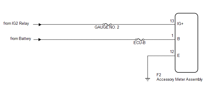
1. w/o Multi-information Display
(a) This circuit is the power source circuit for the accessory meter assembly. This circuit provides two types of power sources; one is a constant power source mainly used as a backup power source, and the other is a power source mainly used for signal transmission.
HINT:
If the accessory meter assembly displays "1:00" when the ignition switch is turned off, then to ON again, the B terminal has a malfunction.
The maximum clock assembly margin of error is -4 to 4 seconds per day when the temperature is between -20°C (-4°F) and 60°C (140°F).
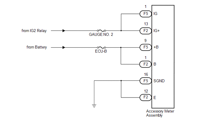
2. w/ Multi-information Display
(a) This circuit is the power source circuit for the accessory meter assembly. This circuit provides two types of power sources; one is a constant power source mainly used as a backup power source, and the other is a power source mainly used for signal transmission.
HINT:
If the accessory meter assembly displays "1:00" when the ignition switch is turned off, then to ON again, the +B terminal has a malfunction.
The maximum clock assembly margin of error is -4 to 4 seconds per day when the temperature is between -20°C (-4°F) and 60°C (140°F).
WIRING DIAGRAM
1. w/o Multi-information Display
2. w/ Multi-information Display
PROCEDURE
|
1. |
CHECK HARNESS AND CONNECTOR |
(a) w/o Multi-information Display
|
(1) Disconnect the F2 connector. |
|
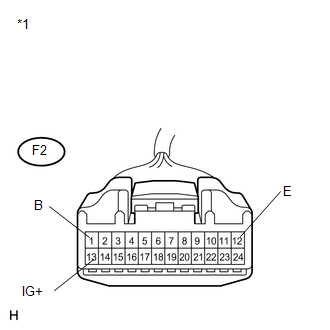
(2) Measure the voltage according to the value(s) in the table below.
Standard Voltage:
|
Tester Connection |
Condition |
Specified Condition |
|---|---|---|
|
F2-1 (B) - Body ground |
Always |
11 to 14 V |
|
F2-13 (IG+) - Body ground |
Ignition switch ON |
11 to 14 V |
(3) Measure the resistance according to the value(s) in the table below.
Standard Resistance:
|
Tester Connection |
Condition |
Specified Condition |
|---|---|---|
|
F2-12 (E) - Body ground |
Always |
Below 1 Ω |
|
*1 |
Front view of wire harness connector (to Accessory Meter Assembly) |
(b) w/ Multi-information Display
|
(1) Disconnect the F2 and F5 connectors. |
|
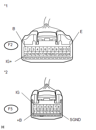
(2) Measure the voltage according to the value(s) in the table below.
Standard Voltage:
|
Tester Connection |
Condition |
Specified Condition |
|---|---|---|
|
F5-1 (IG) - Body ground |
Ignition switch ON |
11 to 14 V |
|
F5-9 (+B) - Body ground |
Always |
11 to 14 V |
|
F2-1 (B) - Body ground |
Always |
11 to 14 V |
|
F2-13 (IG+) - Body ground |
Ignition switch ON |
11 to 14 V |
(3) Measure the resistance according to the value(s) in the table below.
Standard Resistance:
|
Tester Connection |
Condition |
Specified Condition |
|---|---|---|
|
F2-12 (E) - Body ground |
Always |
Below 1 Ω |
|
F5-16 (SGND) - Body ground |
Always |
Below 1 Ω |
|
*1 |
Front view of wire harness connector (to Accessory Meter Assembly) |
|
*2 |
Front view of wire harness connector (to Accessory Meter Assembly ) |
| OK | .gif) |
REPLACE ACCESSORY METER ASSEMBLY |
| NG | |
REPAIR OR REPLACE HARNESS OR CONNECTOR |
 Speed Signal Circuit
DESCRIPTION
The combination meter assembly receives the vehicle speed signal from this circuit.
The wheel speed sensors produce an output that varies according to the vehicle speed.
The wheel spe ...
 Mirror (int)
...
Other materials about Toyota Venza:
Diagnosis System
DIAGNOSIS SYSTEM
1. DESCRIPTION
(a) The power back door ECU (power back door motor unit) controls the power back
door system functions. Power back door system data and Diagnostic Trouble Code (DTC)
can be read through the Data Link Connector 3 (DLC3).
W ...
Engine oil
With the engine at operating temperature and turned off, check the oil level
on the dipstick.
- Checking the engine oil
Park the vehicle on level ground.
After warming up the engine and turning it off, wait more than five minutes for
the oil to ...
Throttle Actuator Control Motor Circuit Low (P2102,P2103)
DESCRIPTION
The throttle actuator is operated by the ECM and opens and closes the throttle
valve using gears.
The opening angle of the throttle valve is detected by the throttle position
sensor, which is mounted on the throttle body. The throttle positio ...

0.1667