Toyota Venza: Power Source Circuit
DESCRIPTION
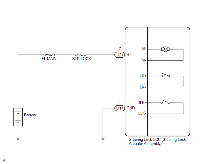
This circuit supplies power source voltage from the battery to terminal B of the steering lock ECU (steering lock actuator assembly). This is used as power source for the CPU, motor, communication, and peripheral circuits.
WIRING DIAGRAM
PROCEDURE
|
1. |
CHECK HARNESS AND CONNECTOR (STEERING LOCK ECU - BODY GROUND) |
|
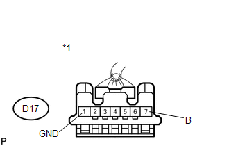
(a) Disconnect the D17 connector from the steering lock ECU (steering lock actuator assembly). |
|
.png)
(b) Measure the resistance according to the value(s) in the table below.
Standard Resistance:
|
Tester Connection |
Condition |
Specified Condition |
|---|---|---|
|
D17-1 (GND) - Body ground |
Always |
Below 1 Ω |
|
*1 |
Front view of wire harness connector (to Steering lock ECU (Steering lock actuator assembly)) |
| NG | .gif) |
REPAIR OR REPLACE HARNESS OR CONNECTOR |
|
.gif)
|
2. |
CHECK HARNESS AND CONNECTOR (STEERING LOCK ECU - BATTERY) |
|
(a) Measure the voltage according to the value(s) in the table below. Standard Voltage:
|
|
| OK | |
PROCEED TO NEXT SUSPECTED AREA SHOWN IN PROBLEM SYMPTOMS TABLE |
| NG | |
REPAIR OR REPLACE HARNESS OR CONNECTOR (STEERING LOCK ECU - BATTERY) |
 Unlock Position Sensor Signal Circuit
DESCRIPTION
The unlock position sensor is one of the components comprising the steering lock
ECU (steering lock actuator assembly). The sensor switch contact closes when the
steering lock is rele ...
 Steering System
...
Other materials about Toyota Venza:
Transponder Key Ecu
Components
COMPONENTS
ILLUSTRATION
Removal
REMOVAL
PROCEDURE
1. REMOVE AIR CONDITIONING UNIT ASSEMBLY
HINT:
Refer to the procedure up to Remove Air Conditioning Unit Assembly (See page
).
2. REMOVE TRANSPONDER KEY ECU ASSEMBLY
(a) ...
Motor Circuit Malfunction (C1522-C1555)
DESCRIPTION
The power steering ECU supplies current to the power steering motor through the
motor circuit.
DTC No.
DTC Detection Condition
Trouble Area
C1522
Motor current sensor malfunction
...
Starting System
Parts Location
PARTS LOCATION
ILLUSTRATION
ILLUSTRATION
System Diagram
SYSTEM DIAGRAM
...

0.1194