Toyota Venza: Power Mirrors do not Return to Memorized Position
SYSTEM DESCRIPTION
If either the M1 or M2 seat memory switch is pressed, the outer mirror control ECU assembly (driver door) detects the seat memory switch status and sends the switch signal to the main body ECU (driver side junction block assembly) via CAN communication. The main body ECU (driver side junction block assembly) sends back reproduction signals to each outer mirror control ECU assembly via CAN communication. When receiving the reproduction signals, each outer mirror control ECU assembly operates the vertical and horizontal mirror motors, which are built into the outer rear view mirror assembly, to adjust the mirror surface to the stored position.
WIRING DIAGRAM
.png)
PROCEDURE
|
1. |
CHECK CAN COMMUNICATION SYSTEM |
(a) Use the Techstream to check if the CAN communication system is functioning
normally (See page .gif) ).
).
OK:
CAN communication DTC is not output.
| NG | .gif) |
GO TO CAN COMMUNICATION SYSTEM (DIAGNOSTIC TROUBLE CODE CHART) |
|
.gif)
|
2. |
CHECK SEAT MEMORY SWITCH FUNCTION |
(a) When any seat memory switch (M1 or M2 switch) is pressed, check that the driver seat moves to the memorized position.
OK:
The driver seat moves to the memorized position.
| NG | |
GO TO POWER SEAT CONTROL SYSTEM (Power Seat does not Return to Memorized Position) |
|
|
3. |
CHECK POWER MIRROR CONTROL FUNCTION (ELECTRICAL REMOTE CONTROL MIRROR FUNCTION) |
(a) Check the electrical remote control mirror function (See page
).
OK:
Electrical remote control mirror function is normal.
| NG | |
GO TO OTHER DIAGNOSIS PROCEDURE |
|
|
4. |
READ VALUE USING TECHSTREAM (MIRROR POSITION MEMORY) |
(a) Connect the Techstream to the DLC3.
(b) Turn the ignition switch ON.
(c) Turn the Techstream on.
(d) Enter the following menus: Body Electrical / Mirror L or Mirror R / Data List.
(e) Read the Data List according to the display on the Techstream.
Mirror L / Mirror R|
Tester Display |
Measurement Item/Range |
Normal Condition |
Diagnostic Note |
|---|---|---|---|
|
Mirror Memory No. 1 |
Mirror position memorized in seat memory switch M1 / ON or OFF |
ON: Memorized OFF: Not memorized |
- |
|
Mirror Memory No. 2 |
Mirror position memorized in seat memory switch M2 / ON or OFF |
ON: Memorized OFF: Not memorized |
- |
|
Mirror Memory No. 3* |
Mirror position memorized in seat memory switch M3 / ON or OFF |
ON: Memorized OFF: Not memorized |
Not applicable |
|
Mirror Memory No. 4* |
Mirror position memorized in seat memory switch M4 / ON or OFF |
ON: Memorized OFF: Not memorized |
Not applicable |
|
Mirror Memory No. 5* |
Mirror position memorized in seat memory switch M5 / ON or OFF |
ON: Memorized OFF: Not memorized |
Not applicable |
|
Mirror Memory No. 6* |
Mirror position memorized in seat memory switch M6 / ON or OFF |
ON: Memorized OFF: Not memorized |
Not applicable |
- *: Although the item is displayed on the Techstream, it is not applicable to this vehicle.
OK:
ON (Memorized) appears on the screen.
| NG | |
GO TO OTHER DIAGNOSIS PROCEDURE (Power Mirror Surface Position is not Memorized) |
|
|
5. |
CHECK MEMORY AND REACTIVATION FUNCTION |
|
(a) Turn the ignition switch ON. |
|
(b) Using the outer mirror switch assembly, turn the mirror surface to the fully left position.
(c) Press the M1 switch while the SET switch is being pressed.
(d) Check that the buzzer sounds for 0.5 seconds and the mirror surface position is memorized.
(e) Using the outer mirror switch assembly, turn the mirror surface to the fully right position.
(f) Press the M1 switch.
(g) Check that the buzzer sounds for 0.1 seconds and the outer mirror automatically moves to the recorded fully left position.
|
Result |
Proceed to |
|---|---|
|
Memory and reactivation functions on both mirrors are not normal |
A |
|
Memory and reactivation functions on driver door mirror are not normal |
B |
|
Memory and reactivation functions on front passenger door mirror are not normal |
C |
|
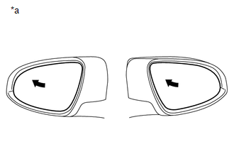
*a |
Turn to Left Fully |
| A | |
REPLACE MAIN BODY ECU (DRIVER SIDE JUNCTION BLOCK ASSEMBLY) |
| C | |
GO TO STEP 8 |
|
|
6. |
REPLACE OUTER REAR VIEW MIRROR ASSEMBLY (DRIVER DOOR) |
(a) Replace the outer rear view mirror assembly (driver door) (See page
).
|
|
7. |
CHECK MEMORY AND REACTIVATION FUNCTION |
|
(a) Turn the ignition switch ON. |
|
(b) Using the outer mirror switch assembly, turn the mirror surface to the fully left position.
(c) Press the M1 switch while the SET switch is being pressed.
(d) Check that the buzzer sounds for 0.5 seconds and the mirror surface position is memorized.
(e) Using the outer mirror switch assembly, turn the mirror surface to the fully right position.
(f) Press the M1 switch.
(g) Check that the buzzer sounds for 0.1 seconds and the outer mirror automatically moves to the recorded fully left position.
OK:
Memory and reactivation function is normal.
Text in Illustration|
*a |
Turn to Left Fully |
| OK | |
END (OUTER REAR VIEW MIRROR ASSEMBLY (DRIVER DOOR) WAS DEFECTIVE) |
| NG | |
REPLACE OUTER MIRROR CONTROL ECU ASSEMBLY (DRIVER DOOR) |
|
8. |
REPLACE OUTER REAR VIEW MIRROR ASSEMBLY (FRONT PASSENGER DOOR) |
(a) Replace the outer rear view mirror assembly (front passenger door) (See page
).
|
|
9. |
CHECK MEMORY AND REACTIVATION FUNCTION |
|
(a) Turn the ignition switch ON. |
|

(b) Using the outer mirror switch assembly, turn the mirror surface to the fully left position.
(c) Press the M1 switch while the SET switch is being pressed.
(d) Check that the buzzer sounds for 0.5 seconds and the mirror surface position is memorized.
(e) Using the outer mirror switch assembly, turn the mirror surface to the fully right position.
(f) Press the M1 switch.
(g) Check that the buzzer sounds for 0.1 seconds and the outer mirror automatically moves to the recorded fully left position.
OK:
Memory and reactivation function is normal.
Text in Illustration|
*a |
Turn to Left Fully |
| OK | |
END (OUTER REAR VIEW MIRROR ASSEMBLY (FRONT PASSENGER DOOR) WAS DEFECTIVE) |
| NG | |
REPLACE OUTER MIRROR CONTROL ECU ASSEMBLY (FRONT PASSENGER DOOR) |
 Power Mirror Surface Position is not Memorized
SYSTEM DESCRIPTION
If either the M1 or M2 seat memory switch is pressed, the outer mirror control
ECU assembly (driver door) detects the switch operation and sends the seat memory
switch signal t ...
 Reverse Shift-linked Function of Power Mirrors does not Operate
SYSTEM DESCRIPTION
On receiving a reverse signal from the park/neutral position switch assembly,
the ECM sends the reverse signal to the main body ECU (driver side junction block
assembly) via CA ...
Other materials about Toyota Venza:
Room Temperature Sensor
Components
COMPONENTS
ILLUSTRATION
Removal
REMOVAL
PROCEDURE
1. DISCONNECT CABLE FROM NEGATIVE BATTERY TERMINAL
NOTICE:
When disconnecting the cable, some systems need to be initialized after the cable
is reconnected (See page ).
2. REMOVE FR ...
Diagnostic Trouble Code Chart
DIAGNOSTIC TROUBLE CODE CHART
If a trouble code is displayed during the DTC check, check the parts listed for
that code in the table below and proceed to the appropriate page.
HINT:
The steering lock ECU does not store DTCs regarding the past problems.
S ...
Precaution
PRECAUTION
1. PRECAUTION FOR DISCONNECTING CABLE FROM NEGATIVE BATTERY TERMINAL
NOTICE:
When disconnecting the cable from the negative (-) battery terminal, initialize
the following systems after the terminal is reconnected.
System Name
...

0.1185