Toyota Venza: Power Back Door Warning Buzzer
Components
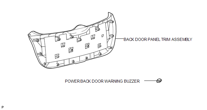
COMPONENTS
ILLUSTRATION
Inspection
INSPECTION
PROCEDURE
1. INSPECT POWER BACK DOOR WARNING BUZZER
|
(a) Measure the resistance according to the value(s) in the table below. HINT: If battery voltage is applied directly to the buzzer, the buzzer will not sound. Standard Resistance:
If the result is not as specified, replace the power back door warning buzzer. |
|
.png)
Removal
REMOVAL
PROCEDURE
1. REMOVE BACK DOOR PANEL TRIM ASSEMBLY
.gif)
2. REMOVE POWER BACK DOOR WARNING BUZZER
|
(a) Disconnect the connector. |
|
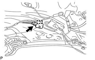
(b) Disengage the clamp to remove the power back door warning buzzer.
Installation
INSTALLATION
PROCEDURE
1. INSTALL POWER BACK DOOR WARNING BUZZER
|
(a) Engage the clamp to install the power back door warning buzzer. |
|
.png)
(b) Connect the connector.
2. INSTALL BACK DOOR PANEL TRIM ASSEMBLY
.gif)
 Power Back Door Touch Sensor
Components
COMPONENTS
ILLUSTRATION
Removal
REMOVAL
PROCEDURE
1. REMOVE UPPER BACK WINDOW PANEL TRIM
2. REMOVE BACK DOOR PANEL TRIM ASSEMBLY
3. DISCONNECT POWER BACK DOOR ROD (for L ...
 Rear Door
...
Other materials about Toyota Venza:
Sending Malfunction (Navigation to APGS) (U0073,U0100,U0140,U0155)
DESCRIPTION
These DTCs are stored when a malfunction occurs in the CAN communication circuit.
DTC No.
DTC Detection Condition
Trouble Area
U0073
CAN bus connection error
CAN communicatio ...
Removal
REMOVAL
PROCEDURE
1. REMOVE UPPER CONSOLE PANEL SUB-ASSEMBLY (w/o Seat Heater System)
2. REMOVE UPPER CONSOLE PANEL SUB-ASSEMBLY (w/ Seat Heater System)
3. REMOVE NO. 2 CONSOLE BOX CARPET
(a) Remove the No. 2 console box carpet.
...
Outer Rear View Mirror Glass
Components
COMPONENTS
ILLUSTRATION
Inspection
INSPECTION
PROCEDURE
1. INSPECT OUTER MIRROR RH
(a) Check the outer mirror heater operation.
(1) Measure the resistance according to the value(s) in the table below.
Standard Resistanc ...

0.1804