Toyota Venza: Power Back Door Closer Switch
Components
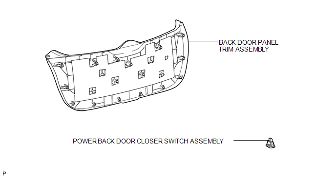
COMPONENTS
ILLUSTRATION
Removal
REMOVAL
PROCEDURE
1. REMOVE BACK DOOR PANEL TRIM ASSEMBLY
.gif)
2. REMOVE POWER BACK DOOR CLOSER SWITCH ASSEMBLY
|
(a) Disconnect the connector. |
|
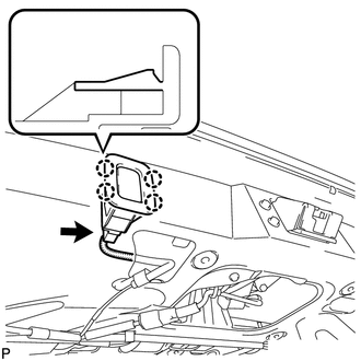
(b) Disengage the 4 claws and remove the power back door closer switch assembly.
Inspection
INSPECTION
PROCEDURE
1. INSPECT POWER BACK DOOR CLOSER SWITCH
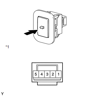
(a) Check that the switch function.
(1) Measure the resistance according to the value(s) in the table below.
Standard Resistance:
|
Tester Connection |
Condition |
Specified Condition |
|---|---|---|
|
4 - 1 |
Pushed (ON) |
Below 1 Ω |
|
4 - 1 |
Free (OFF) |
10 kΩ or higher |
|
*1 |
Component without harness connected (Power Back Door Closer Switch) |
If the result is not as specified, replace the switch.
|
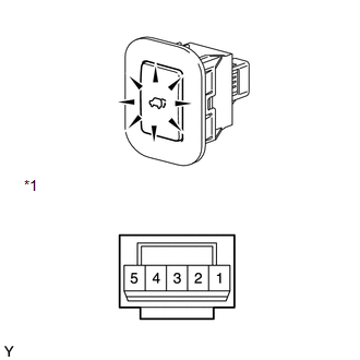
(b) Check that the switch illuminates. (1) Apply battery voltage to the power back door closer switch and check that the switch illuminates. OK:
If the result is not as specified, replace the switch. |
|
Installation
INSTALLATION
PROCEDURE
1. INSTALL POWER BACK DOOR CLOSER SWITCH ASSEMBLY
|
(a) Engage the 4 claws to install the power back door closer switch assembly. |
|
.png)
(b) Connect the connector.
2. INSTALL BACK DOOR PANEL TRIM ASSEMBLY
.gif)
 Removal
REMOVAL
PROCEDURE
1. REMOVE FRONT WHEEL LH
2. REMOVE FRONT FENDER OUTSIDE MOULDING LH
3. REMOVE FRONT FENDER LINER LH
(a) Using a screwdriver, turn the pin 90 degrees and remove the ...
 Power Back Door Control Switch
Components
COMPONENTS
ILLUSTRATION
Inspection
INSPECTION
PROCEDURE
1. INSPECT POWER BACK DOOR OPENER / CLOSER SWITCH
(a) Measure the resistance of the switch.
Standard resistance:
...
Other materials about Toyota Venza:
Alarm
The system sounds the alarm and flashes lights when forcible entry is detected.
- Triggering of the alarm
The alarm is triggered in the following situations when the alarm is set.
• A locked door is unlocked or opened in any way other than by using ...
Installation
INSTALLATION
PROCEDURE
1. INSTALL ECM
(a) Install the bracket to the ECM with the 5 screws.
(b) Install the ECM with the 3 bolts.
Torque:
8.0 N·m {82 kgf·cm, 71 in·lbf}
...
Installation
INSTALLATION
CAUTION / NOTICE / HINT
HINT:
When installing new name plates and emblem, heat the vehicle body, name plates
and emblem using a heat light.
Heating Temperature
Item
Temperature
Vehicle Body
...

0.1372