Toyota Venza: Power Back Door cannot be Closed Using the Power Back Door Closer Switch
DESCRIPTION
When the power back door cannot be closed using the power back door closer switch, either of the following may be malfunctioning: 1) power back door closer switch circuit or 2) power back door ECU (power back door motor unit).
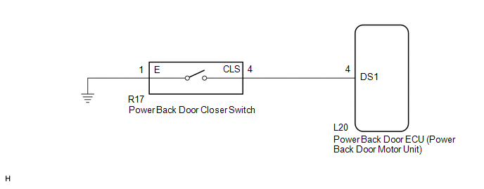
WIRING DIAGRAM
PROCEDURE
|
1. |
READ VALUE USING TECHSTREAM (POWER BACK DOOR CLOSER SWITCH) |
(a) Connect the Techstream to the DLC3.
(b) Turn the ignition switch to ON.
(c) Turn the Techstream on.
(d) Enter the following menus: Body Electrical / Back Door / Data List.
(e) Check the Data List to determine if the power back door closer switch functions properly.
Back Door (Power Back Door ECU)|
Tester Display |
Measurement Item/Range |
Normal Condition |
Diagnostic Note |
|---|---|---|---|
|
PBD Close SW |
Power back door closer switch signal / ON or OFF |
ON: Power back door closer switch on OFF: Power back door closer switch off |
- |
OK:
The power back door closer switch functions as specified in the normal condition column.
| OK | .gif) |
REPLACE POWER BACK DOOR ECU (POWER BACK DOOR MOTOR UNIT) |
|
.gif)
|
2. |
INSPECT POWER BACK DOOR CLOSER SWITCH |
|
(a) Remove the power back door closer switch (See page
|
|
.gif) ).
)..png)
(b) Measure the resistance according to the value(s) in the table below.
Standard Resistance:
|
Tester Connection |
Condition |
Specified Condition |
|---|---|---|
|
4 - 1 |
Pushed (on) |
Below 1 Ω |
|
4 - 1 |
Free (off) |
10 kΩ or higher |
|
*1 |
Component without harness connected (Power Back Door Closer Switch) |
| NG | |
REPLACE POWER BACK DOOR CLOSER SWITCH |
|
|
3. |
CHECK HARNESS AND CONNECTOR (POWER BACK DOOR CLOSER SWITCH - POWER BACK DOOR ECU) |
(a) Disconnect the R17 power back door closer switch and L20 power back door ECU connectors.
(b) Measure the resistance according to the value(s) in the table below.
Standard Resistance:
|
Tester Connection |
Condition |
Specified Condition |
|---|---|---|
|
R17-4 (CLS) - L20-4 (DS1) |
Always |
Below 1 Ω |
|
R17-1 (E) - Body ground |
Always |
Below 1 Ω |
|
R17-4 (CLS) - Body ground |
Always |
10 kΩ or higher |
| OK | |
REPLACE POWER BACK DOOR ECU (POWER BACK DOOR MOTOR UNIT) |
| NG | |
REPAIR OR REPLACE HARNESS OR CONNECTOR |
 Power Back Door cannot be Operated Using Any Switch
DESCRIPTION
When the power back door cannot be operated using any switch, one of the following
may be the cause: 1) initialization of the power back door ECU (power back door
motor unit), 2) powe ...
 Jam Protection Function Activates During Power Back Door Operation
DESCRIPTION
When the jam protection function activates during power back door operation,
one of the following may be the cause: 1) improper fit of back door, or a foreign
object is stuck in the b ...
Other materials about Toyota Venza:
Operation Check
OPERATION CHECK
1. CHECK AUTO OPERATION
NOTICE:
Make sure that initialization is completed before inspection (See page
).
HINT:
When pressing the switch for 0.3 seconds or less, the roof glass moves but auto
operation does not operate.
(a) Turn the i ...
System Diagram
SYSTEM DIAGRAM
Communication Method
Transmitting ECU
Receiver
Signal
Communication Method
Main body ECU (Driver Side Junction Block Assembly)
Power back door ECU (Power back door motor ...
Problem Symptoms Table
PROBLEM SYMPTOMS TABLE
HINT:
Use the table below to help determine the cause of problem symptoms.
If multiple suspected areas are listed, the potential causes of the symptoms
are listed in order of probability in the "Suspected Area" ...

0.1207