Toyota Venza: Personal Light
Components
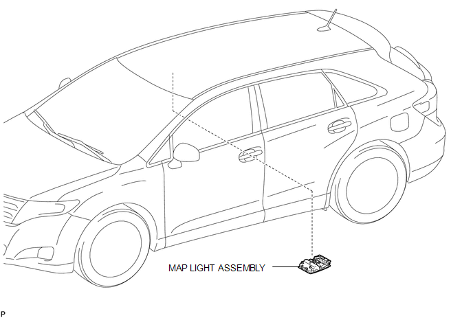
COMPONENTS
ILLUSTRATION
Removal
REMOVAL
PROCEDURE
1. REMOVE MAP LIGHT ASSEMBLY
|
(a) Using a moulding remover, disengage the 2 claws and 2 clips. Text in Illustration
|
|
.png)
(b) Disengage the fastener.
(c) Disconnect each connector and remove the map light assembly.
Installation
INSTALLATION
PROCEDURE
1. INSTALL MAP LIGHT ASSEMBLY
(a) Connect each connector.
|
(b) Engage the fastener. Text in Illustration
|
|
.png)
(c) Engage the 2 claws and 2 clips, and install the map light assembly.
 Luggage Compartment Room Light
Components
COMPONENTS
ILLUSTRATION
Removal
REMOVAL
PROCEDURE
1. REMOVE NO. 2 ROOM LIGHT ASSEMBLY
(a) Using a moulding remover, disengage the claw.
...

Other materials about Toyota Venza:
Installation
INSTALLATION
CAUTION / NOTICE / HINT
HINT:
Use the same procedure for the RH side and LH side.
The procedure listed below is for the LH side.
PROCEDURE
1. INSTALL CURTAIN SHIELD AIRBAG ASSEMBLY
(a) Check that the ignition switch is off. ...
Bank 1 Air-Fuel Ratio Imbalance (P219A,P219C-P219F)
DESCRIPTION
Refer to DTC P0300 (See page ).
Refer to DTC P2195 (See page ).
DTC No.
DTC Detection Condition
Trouble Area
P219A
The difference in air fuel ratios between the cylinders exceeds the ...
Power Back Door cannot be Opened or Closed Using the Power Back Door Switch
DESCRIPTION
When the power back door cannot be opened or closed using the power back door
control switch, one of the following may be malfunctioning: 1) power back door control
switch circuit, 2) power back door ECU (power back door motor unit) or 3) main ...

0.1124