Toyota Venza: Parts Location
PARTS LOCATION
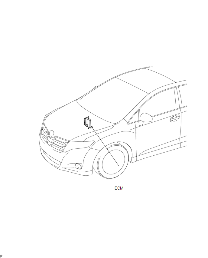
ILLUSTRATION
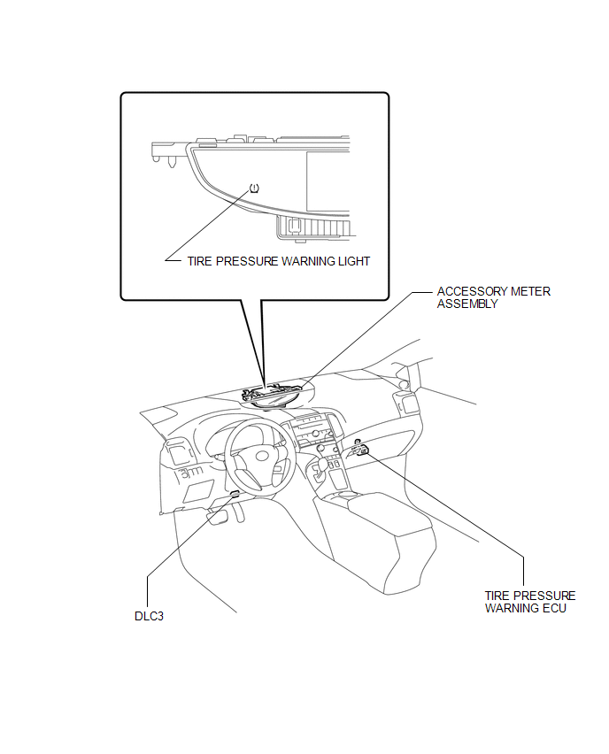
ILLUSTRATION
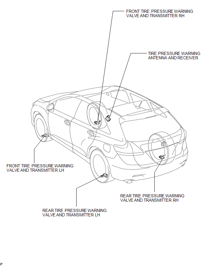
ILLUSTRATION
 Precaution
PRECAUTION
1. PRECAUTION FOR DISCONNECTING THE BATTERY CABLE
NOTICE:
When disconnecting the cable from the negative (-) battery terminal, initialize
the following systems after the cable is recon ...
 System Diagram
SYSTEM DIAGRAM
HINT:
Each tire pressure warning valve and transmitter sends information on the temperature
inside the tire, the transmitter ID and the tire pressure. ...
Other materials about Toyota Venza:
Disassembly
DISASSEMBLY
PROCEDURE
1. REMOVE NO. 2 ANTENNA CORD SUB-ASSEMBLY (w/o Sliding Roof)
2. REMOVE NO. 2 ANTENNA CORD SUB-ASSEMBLY (w/ Sliding Roof)
3. REMOVE VANITY LIGHT ASSEMBLY
(a) Remove the vanity light assembly (See page
).
HINT:
Use the same p ...
Installation
INSTALLATION
PROCEDURE
1. TEMPORARILY TIGHTEN FRONT DISC BRAKE BLEEDER PLUG
(a) Temporarily tighten the front disc brake bleeder plug.
HINT:
Fully tighten the front disc brake bleeder plug after bleeding any air left in
the system.
(b) Install the fron ...
System Description
SYSTEM DESCRIPTION
1. ILLUMINATED ENTRY SYSTEM
(a) The illuminated entry system has the following control functions:
Control
Outline
Lights that Operate
Actuation Area-linked*2
When a registered k ...

0.1693