Toyota Venza: Parking Brake Switch Circuit
DESCRIPTION
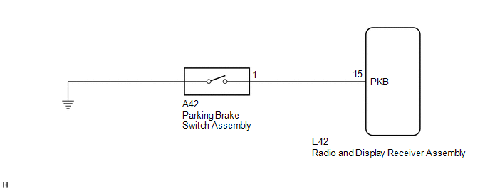
This circuit is from the parking brake switch assembly to the radio and display receiver assembly.
WIRING DIAGRAM
PROCEDURE
|
1. |
CHECK BRAKE WARNING LIGHT |
(a) Check that the brake warning light comes on when the parking brake is applied and goes off when it is released.
OK:
The brake warning light operates as specified above.
| NG | .gif) |
GO TO BRAKE CONTROL / DYNAMIC CONTROL SYSTEMS |
|
.gif)
|
2. |
CHECK HARNESS AND CONNECTOR (PARKING BRAKE SWITCH ASSEMBLY - RADIO AND DISPLAY RECEIVER ASSEMBLY) |
(a) Disconnect the E42 radio and display receiver assembly connector.
(b) Disconnect the A42 parking brake switch assembly connector.
(c) Measure the resistance according to the value(s) in the table below.
Standard Resistance:
|
Tester Connection |
Condition |
Specified Condition |
|---|---|---|
|
E42-15 (PKB) - A42-1 |
Always |
Below 1 Ω |
|
E42-15 (PKB) - Body ground |
Always |
10 kΩ or higher |
| OK | |
PROCEED TO NEXT SUSPECTED AREA SHOWN IN PROBLEM SYMPTOMS TABLE |
| NG | |
REPAIR OR REPLACE HARNESS OR CONNECTOR |
 Illumination Circuit
DESCRIPTION
Power is supplied to the radio and display receiver assembly and steering pad
switch assembly illumination when the light control switch is in the tail or head
position.
WIRING DIAGR ...
 Speaker Circuit
DESCRIPTION
If there is a short in a speaker circuit, the radio and display receiver
assembly detects it and stops output to the speakers.
Thus sound cannot be heard from the speakers ...
Other materials about Toyota Venza:
Diagnosis System
DIAGNOSIS SYSTEM
1. DESCRIPTION
(a) Data of the system can be read from the Data Link Connector 3 (DLC3) of the
vehicle. Therefore, when the system seems to be malfunctioning, use the Techstream
to check for a malfunction and repair it.
2. CHECK DLC3
( ...
Fail-safe Chart
FAIL-SAFE CHART
If any of the following DTCs are stored, the ECM enters fail-safe mode to allow
the vehicle to be driven temporarily or stops fuel injection.
DTC Code
Component
Fail-Safe Operation
Fail-Safe Deact ...
Inspection
INSPECTION
PROCEDURE
1. INSPECT PARK/NEUTRAL POSITION SWITCH ASSEMBLY
(a) Measure the resistance according to the value(s) in the table below
when the shift lever is moved to each position.
Text in Illustration
*1
...

0.1389