Toyota Venza: On-vehicle Inspection
ON-VEHICLE INSPECTION
CAUTION / NOTICE / HINT
HINT:
- Use the same procedure for the RH side and LH side.
- The procedure listed below is for the LH side.
PROCEDURE
1. REMOVE REAR WHEEL
2. SEPARATE REAR FLEXIBLE HOSE
.gif)
3. SEPARATE REAR DISC BRAKE CALIPER ASSEMBLY
4. REMOVE REAR DISC
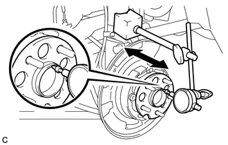
5. INSPECT REAR AXLE HUB BEARING LOOSENESS
|
(a) Using a dial indicator, check for looseness near the center of the axle hub. Maximum looseness: 0.05 mm (0.00196 in.) NOTICE: Ensure that the dial indicator is set perpendicular to the measurement surface. If the looseness exceeds the maximum, replace the rear axle hub and bearing assembly. |
|
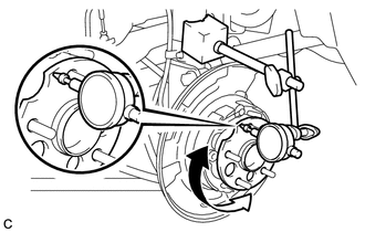
6. INSPECT REAR AXLE HUB RUNOUT
|
(a) Using a dial indicator, check for runout on the surface of the axle hub outside the hub bolt. Maximum runout: 0.08 mm (0.00314 in.) NOTICE: Ensure that the dial indicator is set perpendicular to the measurement surface. If the runout exceeds the maximum, replace the rear axle hub and bearing assembly. |
|
7. INSTALL REAR DISC
8. INSTALL REAR DISC BRAKE CALIPER ASSEMBLY
9. INSTALL REAR FLEXIBLE HOSE
10. INSTALL REAR WHEEL
Torque:
103 N·m {1050 kgf·cm, 76 ft·lbf}
 Components
COMPONENTS
ILLUSTRATION
...
 Removal
REMOVAL
CAUTION / NOTICE / HINT
HINT:
Use the same procedure for the RH side and LH side.
The procedure listed below is for the LH side.
PROCEDURE
1. REMOVE REAR WHEEL
2. SEPAR ...
Other materials about Toyota Venza:
Terminals Of Ecu
TERMINALS OF ECU
1. CHECK TRANSPONDER KEY AMPLIFIER
(a) Disconnect the D21 transponder key amplifier connector.
(b) Measure the resistance according to the value(s) in the table below.
HINT:
Measure the values on the wire harness side with connector dis ...
Inspection
INSPECTION
PROCEDURE
1. INSPECT FRONT DOOR LOCK ASSEMBLY LH
(a) Check the operation of the door lock motor.
(1) Apply battery voltage and check the operation of the door lock motor.
OK:
Measurement Condition
...
Navigation Receiver Assembly Communication Stop Mode
DESCRIPTION
Detection Item
Symptom
Trouble Area
Navigation Receiver Assembly Communication Stop Mode
"Display and Navigation (AVN1)" is not displayed on the "CAN
Bus ...

0.1283