Toyota Venza: On-vehicle Inspection
ON-VEHICLE INSPECTION
CAUTION / NOTICE / HINT
HINT:
- Use the same procedure for the RH side and LH side.
- The procedure listed below is for the LH side.
PROCEDURE
1. REMOVE FRONT WHEEL
2. SEPARATE FRONT DISC BRAKE CALIPER ASSEMBLY
.gif)
3. REMOVE FRONT DISC
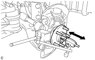
4. INSPECT FRONT AXLE HUB BEARING LOOSENESS
|
(a) Using a dial indicator, check for looseness near the center of the front axle hub. Maximum looseness: 0.05 mm (0.00196 in.) NOTICE: Ensure that the dial indicator is set perpendicular to the measurement surface. If the looseness exceeds the maximum, replace the front axle hub bearing. |
|
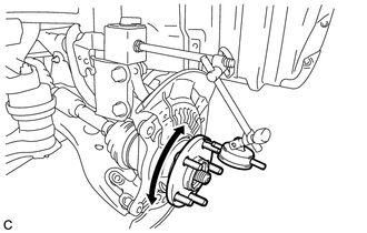
5. INSPECT FRONT AXLE HUB RUNOUT
|
(a) Using a dial indicator, check for runout on the surface of the axle hub outside the hub bolt. Maximum runout: 0.05 mm (0.00196 in.) NOTICE: Ensure that the dial indicator is set perpendicular to the measurement surface. If the runout exceeds the maximum, replace the front axle hub sub-assembly. |
|
6. INSTALL FRONT DISC
7. INSTALL FRONT DISC BRAKE CALIPER ASSEMBLY
8. INSTALL FRONT WHEEL
Torque:
103 N·m {1050 kgf·cm, 76 ft·lbf}
 Components
COMPONENTS
ILLUSTRATION
ILLUSTRATION
...
 Removal
REMOVAL
CAUTION / NOTICE / HINT
HINT:
Use the same procedure for the RH side and LH side.
The procedure listed below is for the LH side.
PROCEDURE
1. REMOVE FRONT WHEEL
2. REMO ...
Other materials about Toyota Venza:
Disassembly
DISASSEMBLY
CAUTION / NOTICE / HINT
HINT:
Use an overhaul stand as necessary.
PROCEDURE
1. REMOVE REAR DIFFERENTIAL FILLER PLUG
(a) Remove the rear differential filler plug and gasket.
2. INSPECT ...
System Diagram
SYSTEM DIAGRAM
1. CAN AND DIRECT LINE SIGNALS
2. INPUT AND OUTPUT SIGNALS OF THE ACCESSORY METER ASSEMBLY
Warning light or indicator light
Communication Signal
Receiver
Communication Line
Sender
...
Reassembly
REASSEMBLY
PROCEDURE
1. INSTALL MULTIPLEX NETWORK DOOR ECU
(a) Connect the connector and install the multiplex network door ECU.
(b) Install the flat cable connector as shown in the illus ...

0.1702