Toyota Venza: On-vehicle Inspection
ON-VEHICLE INSPECTION
PROCEDURE
1. INSPECT GARAGE DOOR OPENER
|
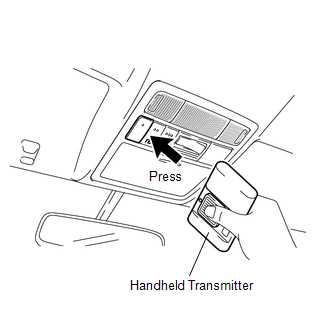
(a) To inspect the garage door opener system, press each switch and check that the LED in the "HomeLink" logo illuminates as illustrated. If one or more of the switches do not cause the LED to illuminate, confirm that the fuse and the wiring to the garage door opener system unit is normal. If the fuse and wiring are normal, and the LED does not illuminate, replace the garage door opener system unit located in the roof console box assembly. |
|
.png)
2. INSPECT GARAGE DOOR OPENER REGISTRATION AND TRANSMITTING
HINT:
Use the KENT-MOORE "HomeLink" tester, and the KENT-MOORE handheld transmitter for this test. First clear the customer's transmitter codes, and then register the code of the KENT-MOORE handheld transmitter to the garage door opener system.
|
(a) Check if the code of the KENT-MOORE handheld transmitter was successfully registered. HINT: If the code of the KENT-MOORE handheld transmitter cannot be registered, replace the garage door opener system unit. |
|
.png)
(b) Press the garage door opener switch that was used to copy the signal from the handheld transmitter. Check if the green LED of the "HomeLink" tester illuminates.
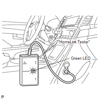
HINT:
If the green LED does not illuminate, replace the garage door opener system unit that is located in the roof console box assembly.
(c) When the inspection is complete, re-register the customer's handheld transmitter codes.
 System Description
SYSTEM DESCRIPTION
1. DESCRIPTION
(a) A maximum of 3 codes for transmitter-code based systems such as garage doors
gates and entry gates can be registered to the vehicle garage door opener system. ...

Other materials about Toyota Venza:
Precaution
PRECAUTION
NOTICE:
When disconnecting the cable from the negative (-) battery terminal, initialize
the following systems after the cable is reconnected.
System Name
See Procedure
Back Door Closer System
...
Installation
INSTALLATION
PROCEDURE
1. INSTALL FRONT SUSPENSION MEMBER BODY MOUNTING REAR CUSHION LH
(a) Temporarily install a new front suspension member body mounting rear
cushion LH while confirming the installation direction.
NOTICE:
Position th ...
Pressure Control Solenoid "D" Performance (Shift Solenoid Valve SLT) (P2714)
SYSTEM DESCRIPTION
The linear solenoid valve (SLT) controls the transmission line pressure for smooth
transmission operation based on signals from the throttle position sensor and the
vehicle speed sensor. The TCM adjusts the current to SLT solenoid valve ...

0.1676