Toyota Venza: On-vehicle Inspection
ON-VEHICLE INSPECTION
PROCEDURE
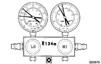
1. INSPECT REFRIGERANT PRESSURE WITH MANIFOLD GAUGE SET
HINT:
This is a method where a manifold gauge set is used to help locate the problem.
(a) Read the manifold gauge pressure when the following conditions are met:
Test conditions:
- Temperature at the air inlet with the switch set at RECIRC is 30 to 35°C (86 to 95°F).
- The engine is running at 1500 rpm.
- The blower speed control switch position is at "HI".
- The temperature control dial position is at "COOL".
- The A/C switch is on.
- Doors are fully open.
- The ignition switch is in a position that enables the A/C compressor to run.
|
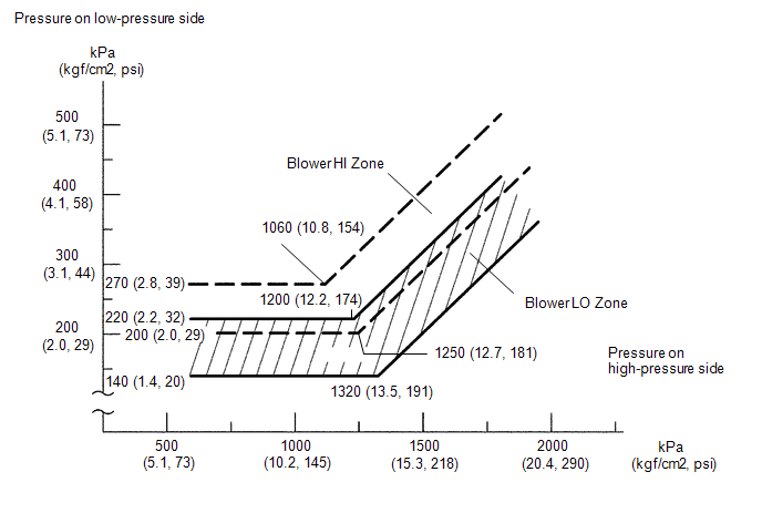
(1) Normally functioning refrigeration system Gauge Reading
|
|
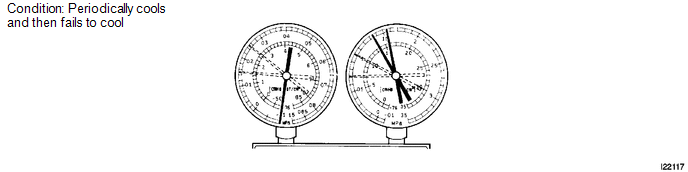
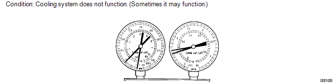
(2) Moisture is present in the refrigeration system.
|
Symptom |
Probable Cause |
Diagnosis |
Corrective Action |
|---|---|---|---|
|
During operation, pressure on low pressure side cycles between normal and vacuum |
|
|
|
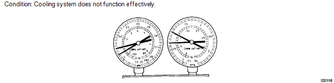
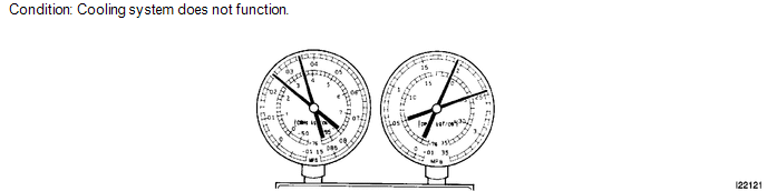
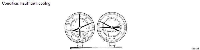
(3) Insufficient cooling
|
Symptom |
Probable Cause |
Diagnosis |
Corrective Action |
|---|---|---|---|
|
Gas leaks from the refrigeration system |
|
|
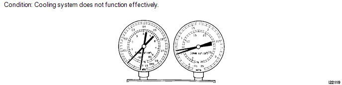
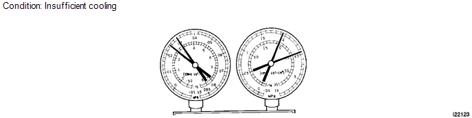
(4) Poor circulation of refrigerant
|
Symptom |
Probable Cause |
Diagnosis |
Corrective Action |
|---|---|---|---|
|
Refrigerant flow is obstructed by dirt inside the pipes of the condenser core |
Receiver is clogged |
Replace condenser |
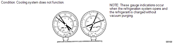
(5) Refrigerant does not circulate.
|
Symptom |
Probable Cause |
Diagnosis |
Corrective Action |
|---|---|---|---|
|
|
Refrigerant does not circulate |
|
(6) Refrigerant is overcharged or cooling effectiveness of condenser is insufficient.
|
Symptom |
Probable Cause |
Diagnosis |
Corrective Action |
|---|---|---|---|
|
|
|
|
(7) Air is present in the refrigeration system.
|
Symptom |
Probable Cause |
Diagnosis |
Corrective Action |
|---|---|---|---|
|
Air in system |
|
|
(8) Expansion valve malfunction
|
Symptom |
Probable Cause |
Diagnosis |
Corrective Action |
|---|---|---|---|
|
Expansion valve may be stuck |
|
Check expansion valve |
(9) Insufficient compressor compression
|
Symptom |
Probable Cause |
Diagnosis |
Corrective Action |
|---|---|---|---|
|
Internal leak in compressor |
|
Replace compressor |
Gauge readings (Reference)
 Refrigerant
...
 Replacement
REPLACEMENT
PROCEDURE
1. RECOVER REFRIGERANT FROM REFRIGERATION SYSTEM
(a) Start up the engine.
(b) Turn the A/C switch on.
(c) Operate the cooler compressor at an engine speed of approximately 1 ...
Other materials about Toyota Venza:
How To Proceed With Troubleshooting
CAUTION / NOTICE / HINT
HINT:
Use the following procedure to troubleshoot the power mirror control
system.
*: Use the Techstream.
PROCEDURE
1.
VEHICLE BROUGHT TO WORKSHOP
NEXT
...
Electrical Key Oscillator(for Center Floor)
Components
COMPONENTS
ILLUSTRATION
Installation
INSTALLATION
PROCEDURE
1. INSTALL ELECTRICAL KEY OSCILLATOR
(a) Engage the clamp and install the electrical key oscillator.
NOTICE:
Be careful when installing the electrical key osci ...
Operation Check
OPERATION CHECK
1. AUTOMATIC LIGHT CONTROL SYSTEM OPERATION CHECK
(a) Turn the ignition switch to ON.
(b) Turn the light control switch to the AUTO position.
(c) Cover the automatic light control sensor.
(d) Check that the taillights and low beam headligh ...

0.1184