Toyota Venza: Navigation Voice Circuit
DESCRIPTION
This circuit is used when the voice switch of the steering pad switch assembly is pushed.
Using this circuit, the navigation receiver assembly sends signals to the stereo component amplifier assembly.
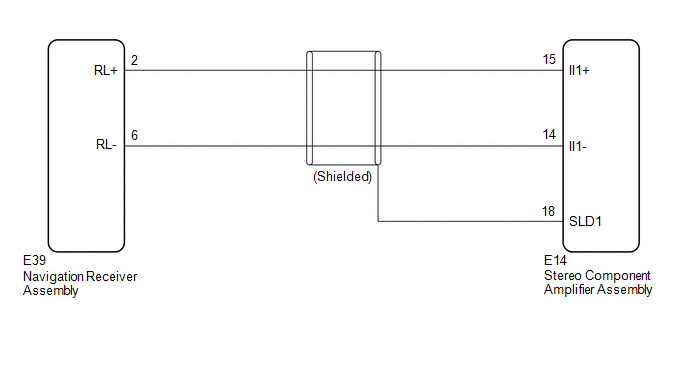
WIRING DIAGRAM
PROCEDURE
|
1. |
CHECK HARNESS AND CONNECTOR (NAVIGATION RECEIVER ASSEMBLY - STEREO COMPONENT AMPLIFIER ASSEMBLY) |
(a) Disconnect the E39 navigation receiver assembly connector.
(b) Disconnect the E14 stereo component amplifier assembly connector.
(c) Measure the resistance according to the value(s) in the table below.
Standard Resistance:
|
Tester connection |
Condition |
Specified condition |
|---|---|---|
|
E39-2 (RL+) - E14-15 (II1+) |
Always |
Below 1 Ω |
|
E39-6 (RL-) - E14-14 (II1-) |
Always |
Below 1 Ω |
|
E14-15 (II1+) - Body ground |
Always |
10 kΩ or higher |
|
E14-14 (II1-) - Body ground |
Always |
10 kΩ or higher |
|
E14-18 (SLD1) - Body ground |
Always |
10 kΩ or higher |
| OK | .gif) |
PROCEED TO NEXT SUSPECTED AREA SHOWN IN PROBLEM SYMPTOMS TABLE |
| NG | |
REPAIR OR REPLACE HARNESS OR CONNECTOR |
 AVC-LAN Circuit
DESCRIPTION
Each unit of the navigation system connected to the AVC-LAN (communication bus)
transmits switch signals via AVC-LAN communication.
If a short to +B or short to ground occurs in the AV ...
 Vehicle Speed Signal Circuit between Stereo Component Amplifier and Combination
Meter
Vehicle Speed Signal Circuit between Stereo Component Amplifier and Combination
Meter
DESCRIPTION
The stereo component amplifier assembly receives a vehicle speed signal from
the combination meter assembly to control the ASL function.
HINT:
A voltage of 12 V or 5 V is outp ...
Other materials about Toyota Venza:
Disassembly
DISASSEMBLY
PROCEDURE
1. REMOVE SEAT ADJUSTER COVER CAP LH
(a) Using a screwdriver wrapped with protective tape, disengage the 3
claws and remove the seat adjuster cover cap LH.
Text in Illustration
*1
...
Disposal
DISPOSAL
CAUTION / NOTICE / HINT
CAUTION:
Before performing pre-disposal deployment of any SRS component, review and closely
follow all applicable environmental and hazardous material regulations. Pre-disposal
deployment may be considered hazardous mate ...
Diagnostic Trouble Code Chart
DIAGNOSTIC TROUBLE CODE CHART
Sliding Roof (Sliding Roof ECU (Sliding Roof Drive Gear Sub-assembly))
DTC Code
Detection Item
Trouble Area
See page
B2341
Sensor (Motor) Failure
...

0.1207