Toyota Venza: Navigation Antenna
Components
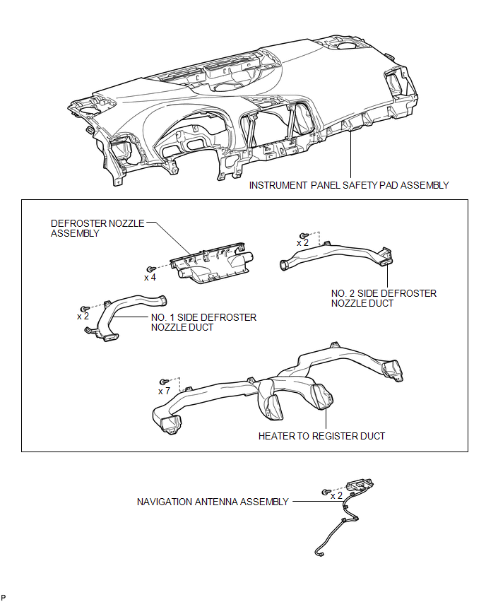
COMPONENTS
ILLUSTRATION
Removal
REMOVAL
PROCEDURE
1. REMOVE INSTRUMENT PANEL SAFETY PAD ASSEMBLY
HINT:
Refer to the procedure up to Remove Instrument Panel Safety Pad Assembly (See
page .gif) ).
).
2. REMOVE NO. 1 SIDE DEFROSTER NOZZLE DUCT
3. REMOVE NO. 2 SIDE DEFROSTER NOZZLE DUCT
4. REMOVE DEFROSTER NOZZLE ASSEMBLY
5. REMOVE HEATER TO REGISTER DUCT
6. REMOVE NAVIGATION ANTENNA ASSEMBLY
|
(a) Disengage the 4 clamps. |
|
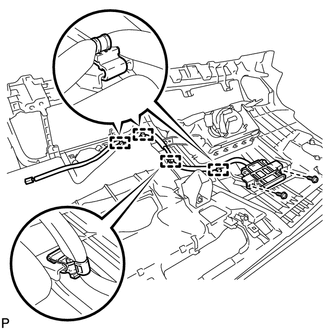
(b) Remove the 2 screws and the navigation antenna assembly.
Installation
INSTALLATION
PROCEDURE
1. INSTALL NAVIGATION ANTENNA ASSEMBLY
|
(a) Install the navigation antenna assembly with the 2 screws. |
|
.png)
(b) Engage the 4 clamps.
2. INSTALL HEATER TO REGISTER DUCT
.gif)
3. INSTALL DEFROSTER NOZZLE ASSEMBLY
4. INSTALL NO. 2 SIDE DEFROSTER NOZZLE DUCT
5. INSTALL NO. 1 SIDE DEFROSTER NOZZLE DUCT
6. INSTALL INSTRUMENT PANEL SAFETY PAD ASSEMBLY
HINT:
Refer to the procedure from Install Roof Headlining Assembly (See page
).


Other materials about Toyota Venza:
Removal
REMOVAL
PROCEDURE
1. REMOVE BRAKE BOOSTER ASSEMBLY
HINT:
Refer to the instructions for Removal of the brake booster assembly (See page
).
2. REMOVE HEADLIGHT LEVELING ECU ASSEMBLY (w/ HID Headlight System)
3. REMOVE STOP LIGHT SWITCH ASSEMBLY
4. ...
Yaw Rate Sensor Output Malfunction (C1448/98)
DESCRIPTION
The skid control ECU receives signals from the yaw rate and acceleration sensor
via the CAN communication system.
The yaw rate sensor has a built-in acceleration sensor and detects the vehicle
condition.
DTC Code
DTC De ...
Disassembly
DISASSEMBLY
PROCEDURE
1. REMOVE STEERING RACK BOOT CLIP (for LH Side)
(a) Using pliers, remove the steering rack boot clip.
2. REMOVE STEERING RACK BOOT CLIP (for RH Side)
HINT:
Perform the same procedure as for the LH side.
3. REMOVE NO. 2 STEERING RAC ...

0.1346