Toyota Venza: Motor Rotation Angle Sensor Malfunction (C1528)
DESCRIPTION
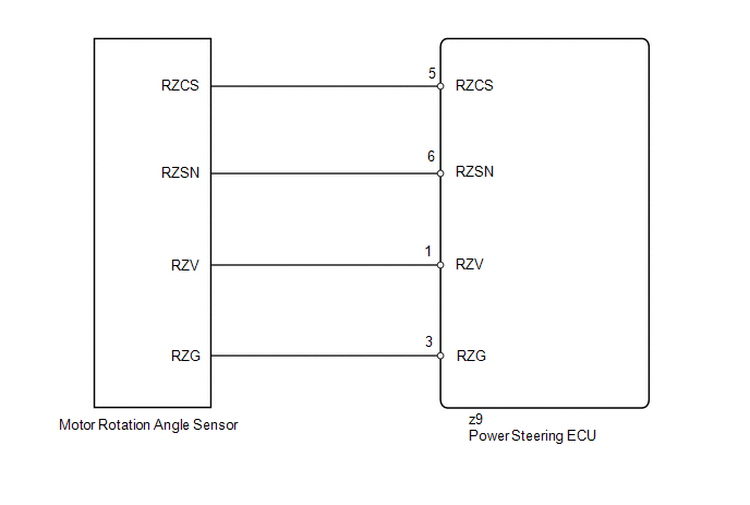
The motor rotation angle sensor detects the motor rotation angle and sends this information to the power steering ECU.
|
DTC No. |
DTC Detection Condition |
Trouble Area |
|---|---|---|
|
C1528 |
Motor rotation angle sensor malfunction |
|
WIRING DIAGRAM
CAUTION / NOTICE / HINT
NOTICE:
If the power steering ECU and steering column assembly have been replaced, perform
the rotation angle sensor initialization and torque sensor zero point calibration
(See page .gif) ).
).
PROCEDURE
|
1. |
CHECK CONNECTOR CONNECTION CONDITION |
(a) Check the installation condition of the motor rotation angle sensor connector.
OK:
Motor rotation angle sensor connector is securely connected to the power steering ECU.
| NG | .gif) |
CONNECT CONNECTOR |
|
.gif)
|
2. |
READ VALUE USING TECHSTREAM (MOTOR ROTATION ANGLE SENSOR) |
(a) Turn the ignition switch off.
(b) Connect the Techstream to the DLC3.
(c) Turn the ignition switch to ON.
(d) Turn the Techstream on.
(e) Enter the following menus: Chassis / EMPS / Data List.
(f) Select the item "Motor Rotation Angle" in the Data List and read the value displayed on the Techstream.
EMPS|
Tester Display |
Measurement Item/Range |
Normal Condition |
Diagnostic Note |
|---|---|---|---|
|
Motor Rotation Angle |
Motor rotation angle/ Min.: 0 deg Max.: 360 deg |
During steering operation, motor rotation angle value changes from 0 to 360° |
The engine is running and steering wheel is being turned. |
OK:
During steering operation, motor rotation angle value changes from 0 to 360°.
| OK | |
REPLACE POWER STEERING ECU |
|
|
3. |
CHECK STEERING COLUMN ASSEMBLY |
|
(a) Disconnect the connector from the motor rotation angle sensor. |
|
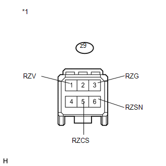
(b) Measure the resistance according to the value(s) in the table below.
Standard Resistance:
|
Tester Connection |
Condition |
Specified Condition |
|---|---|---|
|
z9-6 (RZSN) - z9-3 (RZG) |
Always |
75.2 to 112.8 Ω |
|
z9-1 (RZV) - z9-3 (RZG) |
Always |
27.6 to 41.4 Ω |
|
z9-5 (RZCS) - z9-3 (RZG) |
Always |
73.2 to 110.8 Ω |
|
*1 |
Front view of wire harness connector (to Motor Rotation Angle Sensor) |
| OK | |
REPLACE POWER STEERING ECU |
| NG | |
REPLACE STEERING COLUMN ASSEMBLY |
 IG Power Supply Voltage Malfunction (C1551)
DESCRIPTION
The power steering ECU distinguishes the ignition switch status as ON or off
through the IG power source circuit.
DTC No.
DTC Detection Condition
Troub ...
 Vehicle Speed Signal Malfunction (C1541)
DESCRIPTION
The power steering ECU receives vehicle speed signals from the brake actuator
assembly (skid control ECU) via CAN communication. The ECU provides appropriate
assisting force in accord ...
Other materials about Toyota Venza:
Diagnosis System
DIAGNOSIS SYSTEM
1. CHECK BATTERY VOLTAGE
Standard voltage:
11 to 14 V
If the voltage is below 11 V, recharge the battery before proceeding to the next
step.
2. CHECK DLC3
(a) The ECU uses ISO 15765-4 for communication. The terminal arrangement of the ...
Removal
REMOVAL
PROCEDURE
1. REMOVE FRONT WIPER ARM HEAD CAP
2. REMOVE FRONT WIPER ARM AND BLADE ASSEMBLY LH
3. REMOVE FRONT WIPER ARM AND BLADE ASSEMBLY RH
4. REMOVE FRONT FENDER TO COWL SIDE SEAL LH
5. REMOVE FRONT FENDER TO COWL SIDE SEAL RH
6 ...
If the vehicle becomes stuck
Carry out the following procedures if the tires spin or the vehicle becomes
stuck in mud, dirt, or snow.
Stop the engine. Set the parking
brake and shift the shift lever in “P”.
Stop the engine. Set the parking
brake and shift the shift lever in †...

0.1257