Toyota Venza: MIL Circuit
DESCRIPTION
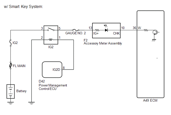
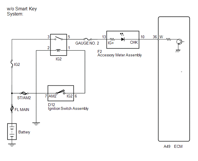
The MIL (Malfunction Indicator Lamp) is used to indicate vehicle malfunctions detected by the ECM. By turning the ignition switch to ON, power is supplied to the MIL circuit, and the ECM provides the circuit ground which illuminates the MIL.
The MIL operation can be checked visually. When the ignition switch is turned to ON, the MIL should be illuminated and should then turn off. If the MIL remains illuminated or is not illuminated, conduct the following troubleshooting procedure. If the ECM detects any trouble, the MIL illuminates. At this time, the ECM records a DTC in the memory.
WIRING DIAGRAM
PROCEDURE
|
1. |
CHECK THAT MIL ILLUMINATES |
(a) Turn the ignition switch to ON.
(b) Check the illumination of the MIL.
|
Result |
Proceed to |
|---|---|
|
MIL remains illuminated (Illuminated at all) |
A |
|
MIL remains off (Does not illuminate at all) |
B |
|
MIL illuminates, but turns off after engine is started |
C |
| B | .gif) |
GO TO STEP 5 |
| C | |
CHECK FOR INTERMITTENT PROBLEMS |
|
.gif)
|
2. |
CHECK WHETHER MIL TURNS OFF |
(a) Connect the Techstream to the DLC3.
(b) Turn the ignition switch to ON.
(c) Turn the Techstream on.
(d) Enter the following menus: Powertrain / Engine / Trouble Codes.
(e) Check if any DTCs have been stored. Note any DTCs.
(f) Clear the DTCs (See page .gif) ).
).
(g) Check if the MIL goes off.
|
Result |
Proceed to |
|---|---|
|
MIL goes off |
A |
|
MIL does not go off |
B |
| A | |
REPAIR CIRCUIT INDICATED BY OUTPUT DTC |
|
|
3. |
CHECK HARNESS AND CONNECTOR (CHECK FOR SHORT IN WIRE HARNESS) |
|
(a) Disconnect the ECM connector. |
|
(b) Turn the ignition switch to ON.
(c) Check if the MIL is illuminated.
|
Result |
Proceed to |
|---|---|
|
MIL is not illuminated |
A |
|
MIL is illuminated |
B |
|
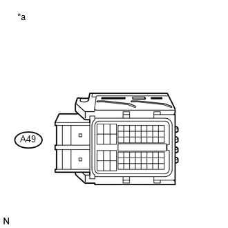
*a |
Front view of wire harness connector (to ECM) |
| A | |
REPLACE ECM |
|
|
4. |
CHECK HARNESS AND CONNECTOR (ACCESSORY METER ASSEMBLY - ECM) |
(a) Disconnect the accessory meter assembly connector.
(b) Disconnect the ECM connector.
(c) Measure the resistance according to the value(s) in the table below.
Standard Resistance (Check for Short):
|
Tester Connection |
Condition |
Specified Condition |
|---|---|---|
|
F2-10 (CHK) or A49-36 (W) - Body ground |
Always |
10 kΩ or higher |
| OK | |
REPLACE ACCESSORY METER ASSEMBLY |
| NG | |
REPAIR OR REPLACE HARNESS OR CONNECTOR (ACCESSORY METER ASSEMBLY - ECM) |
|
5. |
CHECK IF ENGINE STARTS |
(a) Start the engine.
|
Result |
Proceed to |
|---|---|
|
Engine starts |
A |
|
Engine does not start* |
B |
HINT:
*: The Techstream cannot communicate with the ECM.
| B | |
GO TO VC OUTPUT CIRCUIT |
|
|
6. |
CHECK HARNESS AND CONNECTOR (ECM TERMINAL VOLTAGE) |
(a) Disconnect the ECM connector.
(b) Turn the ignition switch to ON.
(c) Measure the voltage according to the value(s) in the table below.
Standard Voltage:
|
Tester Connection |
Switch Condition |
Specified Condition |
|---|---|---|
|
A49-36 (W) - Body ground |
Ignition switch ON |
11 to 14 V |
| OK | |
REPLACE ECM |
|
|
7. |
CHECK HARNESS AND CONNECTOR (ACCESSORY METER ASSEMBLY - ECM) |
(a) Disconnect the accessory meter assembly connector.
(b) Disconnect the ECM connector.
(c) Measure the resistance according to the value(s) in the table below.
Standard Resistance (Check for Open):
|
Tester Connection |
Condition |
Specified Condition |
|---|---|---|
|
F2-10 (CHK) - A49-36 (W) |
Always |
Below 1 Ω |
| OK | |
REPLACE ACCESSORY METER ASSEMBLY |
| NG | |
REPAIR OR REPLACE HARNESS OR CONNECTOR (ACCESSORY METER ASSEMBLY - ECM) |
 Brake Override System
DESCRIPTION
When the vehicle is being driven, depressing the accelerator pedal sensor assembly
and brake pedal will activate the brake override system to restrict driving torque.
The conditions f ...
 Throttle Body
...
Other materials about Toyota Venza:
Pressure Control Solenoid "G" Performance (Shift Solenoid Valve SL4) (P2808)
DESCRIPTION
The TCM uses the vehicle speed signal and signals from the transmission speed
sensors (NC, NT) to detect the actual gear (1st, 2nd, 3rd, 4th, 5th or 6th gear).
Then the TCM compares the actual gear with the shift schedule in the TCM memory
to ...
On-vehicle Inspection
ON-VEHICLE INSPECTION
PROCEDURE
1. INSPECT HOOD SUB-ASSEMBLY
(a) Check that the clearance measurements of areas *1 through *4 are within each
standard range.
Standard Clearance
Area
Measurement
Area
Measureme ...
Unlock Warning Switch Circuit
DESCRIPTION
The key unlock warning switch assembly turns on when the ignition key is inserted
into the ignition key cylinder and turns off when the ignition key is removed.
The main body ECU (driver side junction block assembly) operates the key confinemen ...

0.1275