Toyota Venza: LVL Terminal Circuit
DESCRIPTION
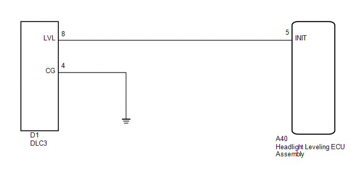
- By connecting terminals LVL and CG of the DLC3, the headlight leveling ECU assembly initializes the height control sensor signal.
WIRING DIAGRAM
PROCEDURE
|
1. |
CHECK HARNESS AND CONNECTOR (DLC3 - HEADLIGHT LEVELING ECU ASSEMBLY) |
|
(a) Disconnect the A40 headlight leveling ECU assembly connector. |
|
(b) Measure the resistance according to the value(s) in the table below.
Standard Resistance:
|
Tester Connection |
Condition |
Specified Condition |
|---|---|---|
|
A40-5 (INIT) - D1-8 (LVL) |
Always |
Below 1 Ω |
|
A40-5 (INIT) - Body ground |
Always |
10 kΩ or higher |
|
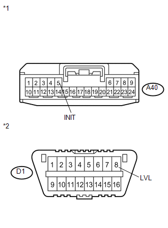
*1 |
Front view of wire harness connector (to Headlight Leveling ECU Assembly) |
|
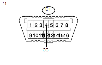
*2 |
DLC3 |
| NG | .gif) |
REPAIR OR REPLACE HARNESS OR CONNECTOR |
|
.gif)
|
2. |
CHECK HARNESS AND CONNECTOR (DLC3 - BODY GROUND) |
|
(a) Measure the resistance according to the value(s) in the table below. Standard Resistance:
|
|
| OK | |
PROCEED TO NEXT SUSPECTED AREA SHOWN IN PROBLEM SYMPTOMS TABLE |
| NG | |
REPAIR OR REPLACE HARNESS OR CONNECTOR |
 Inner Rear View Mirror Power Source Circuit
DESCRIPTION
This circuit detects the state of the ignition switch, and sends it to the inner
rear view mirror assembly.
WIRING DIAGRAM
CAUTION / NOTICE / HINT
NOTICE:
Inspect the fuses for ci ...
 Diagnosis Circuit
DESCRIPTION
The headlight leveling ECU assembly outputs DTC information to the Techstream
via this circuit.
WIRING DIAGRAM
PROCEDURE
1.
CHECK HARNESS AND CONNECTOR (DLC3 ...
Other materials about Toyota Venza:
Back Door cannot be Opened
DESCRIPTION
When the back door cannot be opened, one of the following may be malfunctioning:
1) power back door ECU (power back door motor unit)*1 or back door closer ECU (multiplex
network door ECU)*2, 2) back door lock assembly, 3) back door opener swit ...
Installation
INSTALLATION
PROCEDURE
1. INSTALL SPIRAL CABLE WITH SENSOR SUB-ASSEMBLY
NOTICE:
Do not replace the spiral cable with the battery connected and the ignition
switch on (IG).
Do not rotate the spiral cable with the battery connected and the ig ...
Headlight Leveling ECU Power Source Circuit
DESCRIPTION
This circuit detects the state of the ignition switch, and sends it to the headlight
leveling ECU assembly.
WIRING DIAGRAM
CAUTION / NOTICE / HINT
NOTICE:
Inspect the fuses for circuits related to this system before performing the followin ...

0.1314