Toyota Venza: LVDS Signal Malfunction (from Extension Module) (B1532)
DESCRIPTION
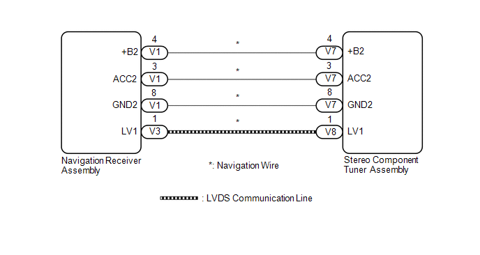
The stereo component tuner assembly and the navigation receiver assembly are connected by the LVDS communication line.
This DTC is stored when an LVDS communication error occurs between the stereo component tuner assembly and the navigation receiver assembly.
|
DTC No. |
DTC Detection Condition |
Trouble Area |
|---|---|---|
|
B1532 |
When any of the following conditions is met:
|
|
HINT:
Even if no malfunction is present, this DTC may be stored depending on the battery condition or engine start voltage.
WIRING DIAGRAM
CAUTION / NOTICE / HINT
NOTICE:
After replacing the stereo component tuner assembly of vehicles subscribed to pay-type satellite radio broadcasts, XM radio ID registration is necessary.
PROCEDURE
|
1. |
CHECK NAVIGATION WIRE (STEREO COMPONENT TUNER ASSEMBLY POWER SOURCE) |
(a) Disconnect the V7 stereo component tuner assembly connector.
(b) Measure the resistance according to the value(s) in the table below.
Standard Resistance:
|
Tester Connection |
Condition |
Specified Condition |
|---|---|---|
|
V7-8 (GND2) - Body ground |
Always |
Below 1 Ω |
(c) Measure the voltage according to the value(s) in the table below.
Standard Voltage:
|
Tester Connection |
Condition |
Specified Condition |
|---|---|---|
|
V7-4 (+B2) - V7-8 (GND2) |
Always |
11 to 14 V |
|
V7-3 (ACC2) - V7-8 (GND2) |
Ignition switch ACC |
11 to 14 V |
| NG | .gif) |
GO TO STEP 4 |
|
.gif)
|
2. |
REPLACE NAVIGATION WIRE |
(a) Replace the navigation wire with a new or known good one (See page
.gif) ).
).
(b) Clear the DTCs (See page ).
(c) Recheck for DTCs and check that no DTCs are output.
OK:
No DTCs are output.
| OK | |
END |
|
|
3. |
REPLACE STEREO COMPONENT TUNER ASSEMBLY |
(a) Replace the stereo component tuner assembly with a new or known good one
(See page ).
(b) Clear the DTCs (See page ).
(c) Recheck for DTCs and check that no DTCs are output.
OK:
No DTCs are output.
| OK | |
END |
| NG | |
REPLACE NAVIGATION RECEIVER ASSEMBLY |
|
4. |
CHECK NAVIGATION WIRE |
(a) Remove the navigation wire (See page ).
(b) Measure the resistance according to the value(s) in the table below.
Standard Resistance::
|
Tester Connection |
Condition |
Specified Condition |
|---|---|---|
|
V1-4 (+B2) - V7-4 (+B2) |
Always |
Below 1 Ω |
|
V1-3 (ACC2) - V7-3 (ACC2) |
Always |
Below 1 Ω |
|
V1-8 (GND2) - V7-8 (GND2) |
Always |
Below 1 Ω |
|
V1-4 (+B2) - Body ground |
Always |
10 kΩ or higher |
|
V1-3 (ACC2) - Body ground |
Always |
10 kΩ or higher |
|
V1-8 (GND2) - Body ground |
Always |
Below 1 Ω |
| OK | |
REPLACE NAVIGATION RECEIVER ASSEMBLY |
| NG | |
REPLACE NAVIGATION WIRE |
 Diagnostic Trouble Code Chart
DIAGNOSTIC TROUBLE CODE CHART
Navigation System
DTC Code
Detection Item
See page
B1532
LVDS Signal Malfunction (from Extension Module)
...
 Voice Recognition Microphone Disconnected (B1579)
DESCRIPTION
The navigation receiver assembly and inner rear view mirror assembly (amplifier
microphone assembly) are connected to each other using the microphone connection
detection signal lines ...
Other materials about Toyota Venza:
Inspection
INSPECTION
PROCEDURE
1. INSPECT ATF TEMPERATURE SENSOR ASSEMBLY
(a) Measure the resistance according to the value(s) in the table below.
Standard Resistance:
Tester Connection
Condition
Sp ...
Transmitter ID not Received in Main Mode (C2126/26)
DESCRIPTION
After all IDs are registered, DTC C2126/26 is set in the tire pressure warning
ECU and the tire pressure warning light blinks for 1 minute and then comes on.
When the tire pressure warning ECU successfully receives radio waves from all
the tr ...
Front Door Speaker
Components
COMPONENTS
ILLUSTRATION
Removal
REMOVAL
PROCEDURE
1. DISCONNECT CABLE FROM NEGATIVE BATTERY TERMINAL
CAUTION:
Wait at least 90 seconds after disconnecting the cable from the negative (-)
battery terminal to disable the SRS system (Se ...

0.1666