Toyota Venza: Lost Communication with ECM / PCM (U0100)
DESCRIPTION
|
DTC No. |
DTC Detection Condition |
Trouble Area |
|---|---|---|
|
U0100 |
No communication from the ECM continues. |
|
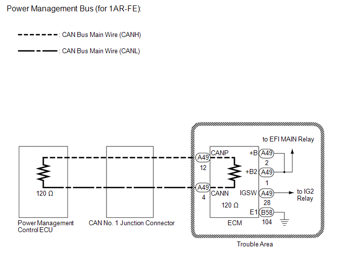
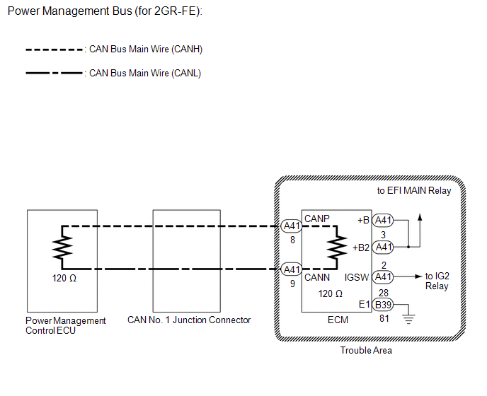
WIRING DIAGRAM
CAUTION / NOTICE / HINT
NOTICE:
- Turn the ignition switch off before measuring the resistances between CAN bus main wires and between CAN bus branch wires.
- Turn the ignition switch off before inspecting CAN bus wires for a ground short.
- After the ignition switch is turned off, check that the key reminder warning system and light reminder warning system are not operating.
- Before measuring the resistance, leave the vehicle as is for at least 1 minute and do not operate the ignition switch, any other switches or the doors. If any doors need to be opened in order to check connectors, open the doors and leave them open.
HINT:
- Operating the ignition switch, any other switches or a door triggers related ECU and sensor communication on the CAN. This communication will cause the resistance value to change.
- Even after DTCs are cleared, if a DTC is stored again after driving the vehicle for a while, the malfunction may be occurring due to vibration of the vehicle. In such a case, wiggling the ECUs or wire harness while performing the inspection below may help determine the cause of the malfunction.
PROCEDURE
|
1. |
RECONFIRM DTC OUTPUT |
(a) Reconfirm DTCs.
HINT:
If CAN power management bus DTC U1002 is output from the power management control ECU (Techstream display: PM2 Gateway), troubleshoot for U1002 and check for malfunctions in the power management main bus circuit.
|
Result |
Proceed to |
|---|---|
|
U1002 is not output from power management control ECU (Techstream display: PM2 Gateway) |
A |
|
U1002 is output from power management control ECU (Techstream display: PM2 Gateway) |
B |
| B | .gif) |
REPAIR CIRCUITS INDICATED BY OUTPUT DTCS |
|
.gif)
|
2. |
CHECK FOR OPEN IN CAN BUS WIRES (ECM MAIN WIRE/POWER MANAGEMENT BUS) |
(a) Turn the ignition switch off.
|
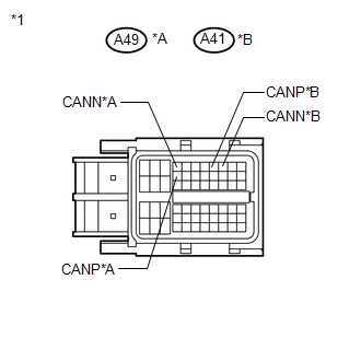
(b) Disconnect the ECM connector. Text in Illustration
|
|
(c) Measure the resistance according to the value(s) in the table below.
Standard Resistance:
|
Tester Connection |
Condition |
Specified Condition |
|---|---|---|
|
A49-12 (CANP) - A49-4 (CANN)*1 |
Ignition switch off |
108 to 132 Ω |
|
A41-8 (CANP) - A41-9 (CANN)*2 |
Ignition switch off |
108 to 132 Ω |
*1: for 1AR-FE
*2: for 2GR-FE
| NG | |
REPAIR OR REPLACE CAN BUS MAIN WIRE OR CONNECTOR (ECM MAIN WIRE) |
|
|
3. |
CHECK ECM POWER SOURCE CIRCUIT |
(a) Check the ECM power source circuit.
HINT:
- for 2GR-FE (See page
.gif) ).
). - for 2AR-FE (See page ).
|
Result |
Proceed to |
|---|---|
|
OK (for 2GR-FE) |
A |
|
OK (for 2AR-FE) |
B |
|
NG |
C |
HINT:
If there is no abnormality in the ECM power source circuit, replace the ECM.
| A | |
REPLACE ECM |
| B | |
REPLACE ECM |
| C | |
REPAIR OR REPLACE ECM POWER SOURCE CIRCUIT |
 Lost Communication with "Door Control Module B" (U0200)
DESCRIPTION
DTC No.
DTC Detection Condition
Trouble Area
U0200
No communication from the outer mirror control ECU assembly (for driver
...
 Lost Communication with AFS ECU (U0182)
DESCRIPTION
DTC No.
DTC Detection Condition
Trouble Area
U0182
No communication from the AFS ECU continues.
AFS ECU ...
Other materials about Toyota Venza:
Using the AUX port/USB port
This port can be used to connect a portable audio device and listen to it
through the vehicle’s speakers.
Open the cover.
Connect the portable audio device.
- Operating portable audio devices connected to the audio system
The volume can be adj ...
Installation
INSTALLATION
PROCEDURE
1. INSTALL FRONT SUSPENSION MEMBER BODY MOUNTING REAR CUSHION LH
(a) Temporarily install a new front suspension member body mounting rear
cushion LH while confirming the installation direction.
NOTICE:
Position th ...
Installation
INSTALLATION
PROCEDURE
1. INSTALL REAR NO. 3 SPEAKER ASSEMBLY
(a) Install the rear No. 3 speaker assembly with the 2 bolts.
(b) Engage the clamp.
2. INSTALL ROOF SIDE INNER GARNISH ASSEMBLY LH
...

0.1277