Toyota Venza: Intake System
Parts Location
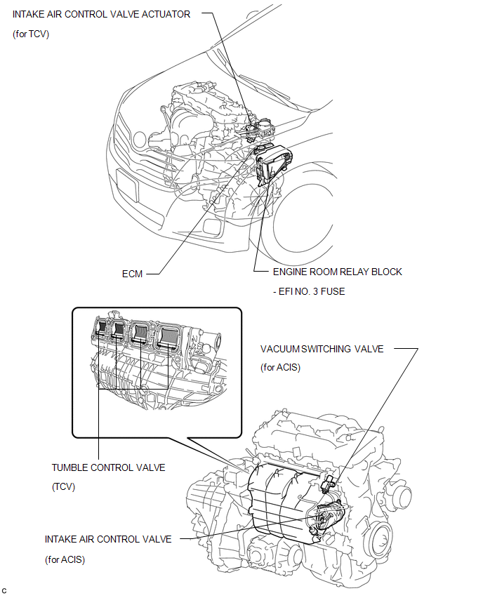
PARTS LOCATION
ILLUSTRATION
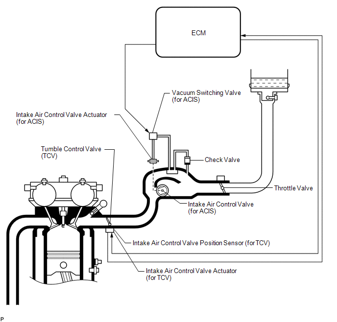
System Diagram
SYSTEM DIAGRAM
On-vehicle Inspection
ON-VEHICLE INSPECTION
PROCEDURE
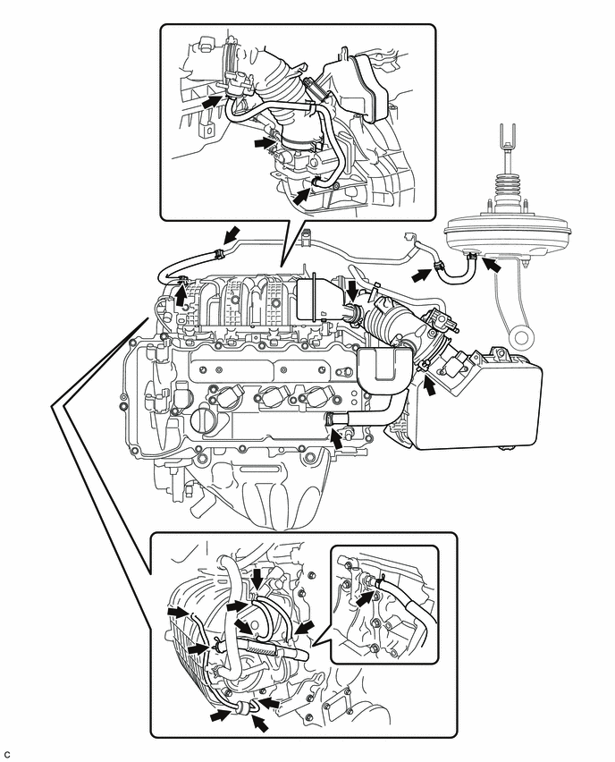
1. INSPECT INTAKE SYSTEM
HINT:
Perform "Inspection After Repair" after repairing vacuum leaks in the intake
system (See page .gif) ).
).
(a) Check that there are no vacuum leaks at the points shown in the illustration.
2. PERFORM INITIALIZATION
(a) Perform "Inspection After Repair" after repairing vacuum leaks in the intake
system (See page ).
3. INSPECT INTAKE AIR CONTROL VALVE (for ACIS)
(a) Connect the Techstream to the DLC3.
(b) Start the engine and turn the Techstream on.
(c) Warm up the engine.
|
(d) Enter the following menus: Powertrain / Engine and ECT / Active Test / Activate the VSV for Intake Control. |
|
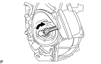
(e) When "Activate the VSV for Intake Control" is turned on, check that the actuator rod operates.
If the operation is not as specified, inspect the intake air control valve, vacuum
tank and check valve (See page ).
(f) When "Activate the VSV for Intake Control" is turned off, check that the actuator rod returns to its original position.
If the operation is not as specified, inspect the intake air control valve and
vacuum hose (See page ).
4. INSPECT INTAKE AIR CONTROL VALVE ACTUATOR (for TCV)
(a) Connect the Techstream to the DLC3.
(b) Turn the ignition switch to ON (do not run the engine).
(c) Turn the Techstream on.
(d) Enter the following menus: Powertrain / Engine and ECT / Active Test / All Data / Control the IAC Duty Ratio.
(1) Set the duty ratio to 60% or -60% for 1 to 3 seconds, and then return the duty ratio to 0%. Check Intake Air Control Position in the Data List.
Specified Condition:
|
Condition (Active Test) |
Specified Condition (Data List) |
|---|---|
|
Control the IAC Duty Ratio set to 60% |
Intake Air Control Position 35° or more |
|
Control the IAC Duty Ratio set to -60% |
Intake Air Control Position 17° or less |
NOTICE:
- Supply power to the intake control valve for 1 to 3 seconds.
- If power is supplied to the intake control valve for less than 1 second, the gear of the tumble control valve does not reach the stopper and the value in the Data List may be incorrect.
- If power is supplied to the intake control valve for more than 3 seconds, the motor may be damaged.
- Do not perform this inspection more than 2 times consecutively.
HINT:
The standard duty ratio for inspections is 60% or -60%. However, if the value in the Data List is not as specified, set the duty ratio to 100% or -100% for 1 to 3 seconds, and check the value in the Data List again.
(e) When the result is not as specified during the Active Test, perform the following procedure.
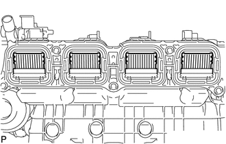
(1) Remove the intake manifold (See page ).
HINT:
When removing the intake manifold, the tumble control valves are half open.
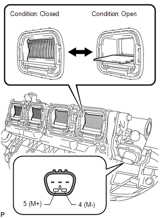
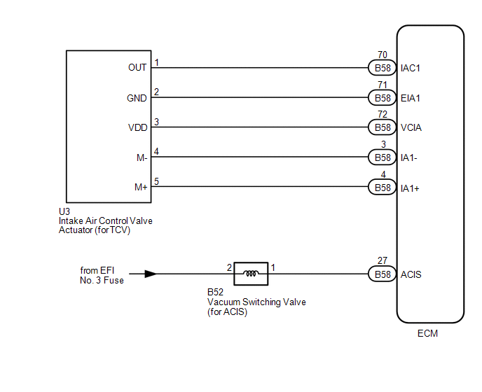
(2) Check that the valves move when connecting the battery to the terminals of the intake air control valve actuator.
Standard:
|
Tester Connection |
Specified Condition |
|---|---|
|
Positive (+) battery voltage applied to terminal 4 (M-), and negative (-) battery voltage applied to terminal 5 (M+) |
Open → Closed |
|
Positive (+) battery voltage applied to terminal 5 (M+), and negative (-) battery voltage applied to terminal 4 (M-) |
Closed → Open |
NOTICE:
- Apply battery voltage for 1 to 3 seconds.
- If battery voltage is applied for more than 3 seconds, the actuator may be damaged.
- Do not allow the lead wires to contact the other terminals.
(3) When the results are not as specified, perform the following inspections.
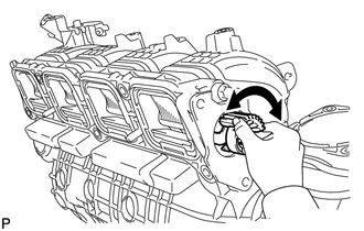
Check that the valves are not cracked or deformed.
Remove the intake air control actuator, and check that the valves move smoothly.
If there are no problems with the valves, inspect the intake air control valve
actuator (See page ).
 Installation
INSTALLATION
PROCEDURE
1. INSTALL ENGINE MOUNTING DAMPER
(a) Install the engine mounting damper with the 3 bolts.
Torque:
9.0 N·m {92 kgf·cm, 80 in·lbf}
...

Other materials about Toyota Venza:
On-vehicle Inspection
ON-VEHICLE INSPECTION
PROCEDURE
1. INSPECT GARAGE DOOR OPENER
(a) To inspect the garage door opener system, press each switch and check
that the LED in the "HomeLink" logo illuminates as illustrated. If one or
more of the switch ...
Lost Communication with AFS ECU (U0182)
DESCRIPTION
DTC No.
DTC Detection Condition
Trouble Area
U0182
No communication from the AFS ECU continues.
AFS ECU branch wire or connector
Power source circuit of AFS E ...
Terminals Of Ecu
TERMINALS OF ECU
1. CHECK MAIN BODY ECU (DRIVER SIDE JUNCTION BLOCK ASSEMBLY)
(a) Disconnect the 2A and 2F main body ECU (driver side junction block assembly)
connectors.
(b) Measure the voltage and resistance according to the value(s) in the table
be ...

0.1442