Toyota Venza: Installation
INSTALLATION
PROCEDURE
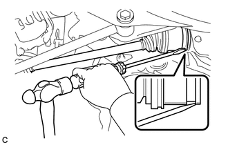
1. INSTALL REAR DRIVE SHAFT ASSEMBLY
|
(a) Align the shaft splines and install the rear drive shaft assembly using a screwdriver and hammer. NOTICE:
|
|
2. INSTALL REAR AXLE CARRIER SUB-ASSEMBLY
.gif)
3. INSPECT REAR STRUT ROD ASSEMBLY
4. INSTALL NO. 3 PARKING BRAKE CABLE ASSEMBLY
5. INSTALL REAR AXLE HUB AND BEARING ASSEMBLY
6. INSTALL REAR SPEED SENSOR
7. INSTALL REAR DISC
8. INSTALL REAR DISC BRAKE CALIPER ASSEMBLY
9. INSTALL REAR AXLE SHAFT NUT
(a) Clean the threaded parts on the drive shaft and axle shaft nut using a non-residue solvent.
NOTICE:
- Be sure to perform this work for a new drive shaft.
- Keep the threaded parts free of oil and foreign objects.
|
(b) Install a new rear axle shaft nut. Torque: 294 N·m {2998 kgf·cm, 217 ft·lbf} |
|
.png)
(c) Using a chisel and hammer, stake the rear axle shaft nut.
10. INSTALL REAR WHEEL
Torque:
103 N·m {1050 kgf·cm, 76 ft·lbf}
11. STABILIZE SUSPENSION
12. INSPECT AND ADJUST DIFFERENTIAL OIL
13. INSPECT AND ADJUST REAR WHEEL ALIGNMENT
HINT:
(See page )
14. CHECK ABS SPEED SENSOR SIGNAL
HINT:
(See page )
 Reassembly
REASSEMBLY
PROCEDURE
1. INSTALL REAR DRIVE SHAFT DUST COVER
(a) Using SST and a steel plate, install a new rear drive shaft dust
cover to the rear drive shaft inboard joint assembly. ...

Other materials about Toyota Venza:
XM Tuner Antenna Disconnected (B15FE,B15FF)
DESCRIPTION
These DTCs are stored when a malfunction occurs in the roof antenna assembly
which is connected to the stereo component tuner assembly.
DTC No.
DTC Detection Condition
Trouble Area
B15FE
...
Occupant Classification Ecu
Components
COMPONENTS
ILLUSTRATION
ILLUSTRATION
On-vehicle Inspection
ON-VEHICLE INSPECTION
CAUTION / NOTICE / HINT
CAUTION:
Be sure to follow the correct removal and installation procedures of the occupant
classification ECU.
PROCEDURE
1. ...
Compressor Lock Sensor Circuit (B1422/22)
SYSTEM DESCRIPTION
The ECM sends the engine speed signal to the A/C amplifier via CAN communication.
The A/C amplifier reads the difference between compressor speed and engine speed.
When the difference becomes too large, the A/C amplifier determines that ...

0.1705