Toyota Venza: Installation
INSTALLATION
PROCEDURE
1. TEMPORARILY TIGHTEN PROPELLER WITH CENTER BEARING SHAFT ASSEMBLY
|
(a) Remove SST from the transfer. SST: 09325-20010 |
|
.png)
(b) Install the propeller with center bearing shaft assembly.
NOTICE:
- Be careful not to damage the oil seal.
- Be careful not to damage the universal joint boot when installing the propeller shaft.
|
(c) Align the matchmarks on the rear propeller shaft and electromagnetic control coupling assembly and install the 4 nuts and 4 washers temporarily. NOTICE: Do not allow grease to adhere to be bolts or washers. Text in Illustration
|
|
.png)
|
(d) Temporarily install the propeller with center bearing shaft assembly with the 4 bolts, 2 No. 1 center support bearing washers and 2 No. 2 center support bearing washers. NOTICE:
|
|
.png)
|
(e) Fully tighten the 4 nuts. Torque: 37 N·m {379 kgf·cm, 27 ft·lbf} |
|
.png)
2. FULLY TIGHTEN PROPELLER WITH CENTER BEARING SHAFT ASSEMBLY
SST: 09370-50010
(a) Remove the piece of cloth or equivalent from the universal joint.
(b) Depress the brake pedal and hold it.
|
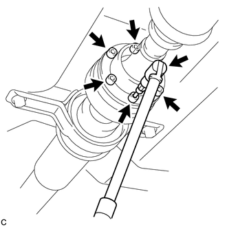
(c) Using a hexagon wrench (6 mm), tighten the 6 bolts. Torque: 26 N·m {265 kgf·cm, 19 ft·lbf} |
|
|
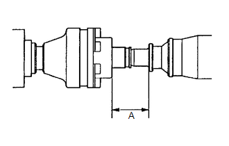
(d) With the vehicle unloaded, adjust the dimension between the rear side of the cover and shaft as shown in the illustration. Length A: 65.5 to 70.5 mm (2.579 to 2.776 in.) |
|
(e) With the vehicle unloaded, adjust the front and rear dimensions between the edge surface of the center support bearing and the edge surface of the cushion respectively as shown in the illustration, and then tighten the bolts.
Length A:
11.5 to 13.5 mm (0.453 to 0.532 in.)
Text in Illustration|
*1 |
No. 1 Center Support Bearing Assembly |
|
*2 |
No. 2 Center Support Bearing Assembly |
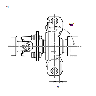
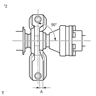
(f) Check that the center line of the bracket is at a right angle to the shaft axial direction.
|
(g) Fully tighten the 4 bolts. Torque: 37 N·m {375 kgf·cm, 27 ft·lbf} |
|
3. INSTALL CENTER EXHAUST PIPE ASSEMBLY (for 1AR-FE)
.gif)
4. INSTALL CENTER EXHAUST PIPE ASSEMBLY (for 2GR-FE)
5. INSTALL TAIL EXHAUST PIPE ASSEMBLY (for 1AR-FE)
6. INSTALL TAIL EXHAUST PIPE ASSEMBLY (for 2GR-FE)
7. INSPECT AND ADJUST TRANSFER OIL
(See page )
8. INSPECT FOR EXHAUST GAS LEAK
9. INSPECT AND ADJUST JOINT ANGLE
(a) If any vibration or noise occurs, perform joint angle check as follows and replace the No. 2 center support bearing washer with a proper one.
(1) Turn the propeller shaft several times by hand to stabilize the center support bearings.
(2) Using a jack, raise and lower the differential to stabilize the differential mounting cushion.
NOTICE:
Measure the joint angle while the vehicle is lifted using a 4 pillar lift or while working in a pit.
(3) Remove the transfer dynamic damper.
(4) Using SST, measure the propeller shaft installation angle (A) and intermediate shaft installation angle (B) as shown in the following illustration.
.png)
No. 1 joint angle:
(A) - (B) = -3.69° to -1.69°
Text in Illustration|
*1 |
No. 1 joint angle |
|
*2 |
No. 4 joint angle |
(5) Using SST, measure the rear propeller shaft installation angle (C) and rear differential installation angle (D) as shown in the preceding illustration.
No. 4 joint angle:
(C) - (D) = 1.63° to 3.63°
(6) If the calculated amount is not within the specification, adjust it with the No. 2 center support bearing washer.
NOTICE:
- Make sure to use a washer of the same thickness on both right and left sides.
- Do not use 2 or more washers on a bolt. Washer Thickness
Thickness mm (in.)
3.2 (0.126)
4.5 (0.177)
6.5 (0.256)
9.0 (0.354)
(7) Install the transfer dynamic damper.
Torque:
26 N·m {265 kgf·cm, 19 ft·lbf}
 Inspection
INSPECTION
PROCEDURE
1. INSPECT UNIVERSAL JOINT SPIDER ASSEMBLY
(a) Check the spider bearing axial play by turning the flange while holding
the shaft tightly.
HINT:
If necessar ...
 Reassembly
REASSEMBLY
PROCEDURE
1. INSTALL NO. 1 CENTER SUPPORT BEARING ASSEMBLY
(a) Set the No. 1 center support bearing on the intermediate shaft as
shown in the illustration.
NOTICE:
M ...
Other materials about Toyota Venza:
Power Seat Power Easy Access System Function does not Operate
DESCRIPTION
When the ignition switch is off and shift lever is in P, the power seat slides
rearward when the seat belt tongue plate is disengaged from the front seat inner
belt assembly LH (auto away function). Also the power seat slides forward when the ...
Throttle Actuator Control Motor Circuit Low (P2102,P2103)
DESCRIPTION
The throttle actuator is operated by the ECM and opens and closes the throttle
valve using gears.
The opening angle of the throttle valve is detected by the throttle position
sensor, which is mounted on the throttle body. The throttle positio ...
IG Power Supply Voltage Malfunction (C1551)
DESCRIPTION
The power steering ECU distinguishes the ignition switch status as ON or off
through the IG power source circuit.
DTC No.
DTC Detection Condition
Trouble Area
C1551
IG power source ci ...

0.144