Toyota Venza: Installation
INSTALLATION
PROCEDURE
1. INSTALL CHECK VALVE GROMMET
(a) Install a new check valve grommet to the brake booster assembly.
2. INSTALL BRAKE VACUUM CHECK VALVE ASSEMBLY
(a) Install the brake vacuum check valve assembly to the brake booster assembly.
3. INSTALL BRAKE MASTER CYLINDER PUSH ROD CLEVIS
(a) Temporarily install the lock nut and brake master cylinder push rod clevis to the brake booster assembly.
|
(b) Set the push rod length as shown in the illustration. Text in Illustration
Standard length*1: 155.1 to 156.1 mm (6.11 to 6.15 in.) |
|
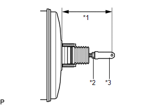
(c) Tighten the lock nut.
Torque:
26 N·m {265 kgf·cm, 19 ft·lbf}
4. INSTALL BRAKE BOOSTER GASKET
|
(a) Install a new brake booster gasket to the brake booster assembly. |
|
.png)
5. INSTALL BRAKE BOOSTER ASSEMBLY
|
(a) Install the brake booster assembly to the body with the 4 nuts. Torque: 13 N·m {130 kgf·cm, 9 ft·lbf} NOTICE: Do not damage the brake lines. |
|
.png)
6. INSTALL PUSH ROD PIN
|
(a) Apply lithium soap base glycol grease to the push rod pin. |
|
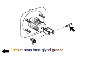
(b) Connect the brake master cylinder push rod clevis to the brake pedal sub-assembly, and install the push rod pin and a new clip as shown in the illustration.
7. INSTALL NO. 1 VACUUM HOSE CONNECTOR (for 1AR-FE)
|
(a) Install the No. 1 vacuum hose connector with the 2 nuts. Torque: 5.4 N·m {55 kgf·cm, 48 in·lbf} |
|
.png)
(b) Connect the vacuum hose to the brake booster assembly, and slide the clip to secure the vacuum hose.
8. CONNECT VACUUM HOSE (for 2GR-FE)
|
(a) Connect the vacuum hose to the brake booster assembly, and slide the clip to secure the vacuum hose. |
|
.png)
9. INSTALL BRAKE MASTER CYLINDER SUB-ASSEMBLY
.gif)
10. FILL RESERVOIR WITH BRAKE FLUID
11. BLEED BRAKE MASTER CYLINDER
12. BLEED BRAKE LINE
13. INSPECT FOR BRAKE FLUID LEAK
14. INSPECT FLUID LEVEL IN RESERVOIR
15. INSPECT AND ADJUST BRAKE PEDAL
HINT:
See page
16. INSTALL SECURITY HORN ASSEMBLY (w/ Security Horn)
17. INSTALL AIR CLEANER CASE (for 1AR-FE)
18. INSTALL AIR CLEANER CASE (for 2GR-FE)
19. INSTALL AIR CLEANER FILTER ELEMENT SUB-ASSEMBLY
20. INSTALL AIR CLEANER CAP SUB-ASSEMBLY (for 1AR-FE)
21. INSTALL AIR CLEANER CAP SUB-ASSEMBLY (for 2GR-FE)
22. INSTALL OUTER COWL TOP PANEL
23. INSTALL WINDSHIELD WIPER MOTOR AND LINK ASSEMBLY
24. INSTALL COWL TOP VENTILATOR LOUVER SUB-ASSEMBLY
25. INSTALL FRONT FENDER TO COWL SIDE SEAL RH
26. INSTALL FRONT FENDER TO COWL SIDE SEAL LH
27. INSTALL FRONT WIPER ARM AND BLADE ASSEMBLY RH
28. INSTALL FRONT WIPER ARM AND BLADE ASSEMBLY LH
29. INSTALL FRONT WIPER ARM HEAD CAP
 Inspection
INSPECTION
PROCEDURE
1. INSPECT BRAKE VACUUM CHECK VALVE ASSEMBLY
(a) Check that there is ventilation from the booster to the engine, and
no ventilation from the engine to the booste ...
 Brake Fluid
...
Other materials about Toyota Venza:
Removal
REMOVAL
PROCEDURE
1. ALIGN FRONT WHEELS FACING STRAIGHT AHEAD
2. DISCONNECT CABLE FROM NEGATIVE BATTERY TERMINAL
NOTICE:
When disconnecting the cable, some systems need to be initialized after the cable
is reconnected (See page ).
3. REMOVE FRONT WHEE ...
Dtc Check / Clear
DTC CHECK / CLEAR
1. DTC CHECK/CLEAR (When Using the Techstream)
(a) Check for DTCs.
(1) Connect the Techstream to the DLC3.
(2) Turn the ignition switch to ON.
(3) Turn the Techstream on.
(4) Read the DTCs following the prompts on the Techstream. Enter ...
Problem Symptoms Table
PROBLEM SYMPTOMS TABLE
Use the table below to help determine the cause of problem symptoms. If multiple
suspected areas are listed, the potential causes of the symptoms are listed in order
of probability in the "Suspected Area" column of the tab ...

0.1719