Toyota Venza: Installation
INSTALLATION
CAUTION / NOTICE / HINT
HINT:
- Use the same procedure for the LH side and RH side.
- The following procedure is for the LH side.
- If the sensor rotor needs to be replaced, replace it together with the front drive shaft assembly.
PROCEDURE
1. INSTALL FRONT SPEED SENSOR
|
(a) Install the resin clamp and front speed sensor with the bolt. Torque: 8.5 N·m {87 kgf·cm, 75 in·lbf} NOTICE:
|
|
|
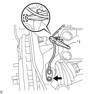
(b) Temporarily install the No. 1 sensor clamp. NOTICE: Be sure to insert the No. 1 sensor clamp claw into the stopper hole while installing the No. 1 sensor clamp. Text in Illustration
|
|
|
(c) Install the front brake flexible hose and No. 1 sensor clamp together to the shock absorber with the bolt. Torque: 19 N·m {194 kgf·cm, 14 ft·lbf} NOTICE:
|
|
|
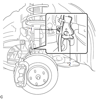
(d) Install the No. 2 sensor clamp to the body with the bolt. Torque: 8.0 N·m {82 kgf·cm, 71 in·lbf} Text in Illustration
|
|
.png)
|
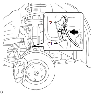
(e) Install the 2 clamps and connect the front speed sensor connector. |
|
.png)
2. INSTALL FRONT FENDER LINER LH
.gif)
3. INSTALL FRONT FENDER OUTSIDE MOULDING LH
4. INSTALL FRONT WHEEL
Torque:
103 N·m {1050 kgf·cm, 76 ft·lbf}
5. CONNECT CABLE TO NEGATIVE BATTERY TERMINAL
NOTICE:
When disconnecting the cable, some systems need to be initialized after the cable
is reconnected (See page ).
6. CHECK FOR SPEED SENSOR SIGNAL
HINT:
(See page )
 Removal
REMOVAL
CAUTION / NOTICE / HINT
HINT:
Use the same procedure for the LH side and RH side.
The following procedure is for the LH side.
If the sensor rotor needs to be replaced, repla ...

Other materials about Toyota Venza:
Relay
On-vehicle Inspection
ON-VEHICLE INSPECTION
PROCEDURE
1. INSPECT DOME CUT RELAY
(a) Measure the resistance according to the value(s) in the table below.
Standard Resistance:
Tester Connection
Condition
...
Air Conditioning Amplifier Communication Stop Mode
DESCRIPTION
Detection Item
Symptom
Trouble Area
Air Conditioning Amplifier Communication Stop Mode
"Air Conditioner" is not displayed on "CAN Bus Check" screen
o ...
Electrical Key Oscillator(for Rear Side)
Components
COMPONENTS
ILLUSTRATION
Removal
REMOVAL
PROCEDURE
1. REMOVE REAR BUMPER PLATE LH
2. REMOVE REAR BUMPER PLATE RH
3. REMOVE REAR BUMPER ASSEMBLY
4. REMOVE ELECTRICAL KEY ANTENNA
(a) Disconnect the connector.
...

0.1317