Toyota Venza: Installation
INSTALLATION
PROCEDURE
1. INSTALL BRAKE ACTUATOR ASSEMBLY
|
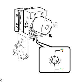
(a) Install the brake actuator assembly to the brake actuator bracket assembly with the 2 nuts. Torque: 8.0 N·m {82 kgf·cm, 71 in·lbf} NOTICE:
|
|
2. INSTALL BRAKE ACTUATOR WITH BRACKET
|
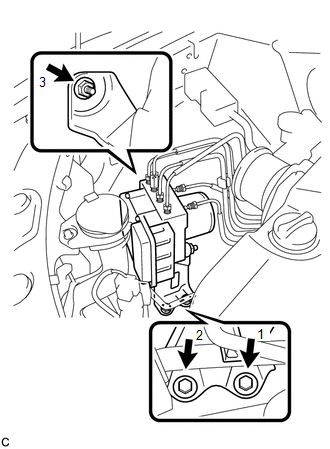
(a) Install the brake actuator with bracket to the body with the nut and 2 bolts. Torque: 19 N·m {194 kgf·cm, 14 ft·lbf} NOTICE:
|
|
|
(b) Connect the brake actuator connector. NOTICE:
|
|
|
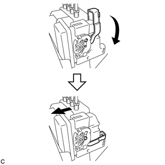
(c) Temporarily tighten each brake line to the correct positions of the brake actuator with bracket as shown in the illustration. Text in Illustration
|
|
.png)
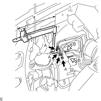
(d) Using a union nut wrench, fully tighten 4 brake lines (A).
 Text in Illustration
|
*a |
Torque Wrench Fulcrum Length |
 |
Flare Nut A (10 mm) |
.png) |
Flare Nut B (12 mm) |
Torque:
Specified Tightening Torque :
15 N·m {155 kgf·cm, 11 ft·lbf}
HINT:
- Calculate the torque wrench reading when changing the fulcrum length
for the torque wrench (See page
.gif) ).
).
- When using a union nut wrench (fulcrum length of 22 mm (0.866 in.))
+ torque wrench (fulcrum length of 250 mm (9.84 in.)):
14 N*m (142 kgf*cm, 10 ft.*lbf)
(e) Using a union nut wrench, fully tighten 2 brake lines (B).
Torque:
Specified Tightening Torque :
20 N·m {199 kgf·cm, 14 ft·lbf}
HINT:
- Calculate the torque wrench reading when changing the fulcrum length
for the torque wrench (See page ).
- When using a union nut wrench (fulcrum length of 20 mm (0.787 in.))
+ torque wrench (fulcrum length of 250 mm (9.84 in.)):
18 N*m (184 kgf*cm, 13 ft.*lbf)
|
(f) Install the clamp of the suction hose sub-assembly to the brake actuator bracket assembly. |
|
.png)
3. INSTALL RADIATOR RESERVE TANK ASSEMBLY
|
(a) Install the radiator reserve tank assembly. |
|
.png)
(b) Install the radiator reserve tank cap assembly.
4. FILL RESERVOIR WITH BRAKE FLUID
5. BLEED BRAKE MASTER CYLINDER
6. BLEED BRAKE LINE
7. INSPECT FLUID LEVEL IN RESERVOIR
8. INSPECT FOR BRAKE FLUID LEAK
9. CONNECT CABLE TO NEGATIVE BATTERY TERMINAL
NOTICE:
When disconnecting the cable, some systems need to be initialized after the cable
is reconnected (See page ).
10. PERFORM ENGINE VARIANT LEARNING
(See page )
11. INSPECT BRAKE ACTUATOR USING TECHSTREAM
(See page )
 Removal
REMOVAL
PROCEDURE
1. DISCONNECT CABLE FROM NEGATIVE BATTERY TERMINAL
NOTICE:
When disconnecting the cable, some systems need to be initialized after the cable
is reconnected (See page ).
2. RE ...
 Brake Pedal Load Sensing Switch
On-vehicle Inspection
ON-VEHICLE INSPECTION
PROCEDURE
1. INSPECT BRAKE PEDAL LOAD SENSING SWITCH
NOTICE:
Do not remove the brake pedal load sensing switch from the brake pedal
suppo ...
Other materials about Toyota Venza:
Problem Symptoms Table
PROBLEM SYMPTOMS TABLE
HINT:
Use the table below to help determine the cause of problem symptoms.
If multiple suspected areas are listed, the potential causes of the symptoms
are listed in order of probability in the "Suspected Area" ...
Reassembly
REASSEMBLY
PROCEDURE
1. INSTALL FUEL PUMP ASSEMBLY WITH FILTER
HINT:
Perform "Inspection After Repair" after replacing the fuel pump (See page
).
(a) Apply gasoline to a new O-ring. Then install the O-ring and spacer
to the fuel ...
Installation
INSTALLATION
CAUTION / NOTICE / HINT
HINT:
Use the same procedure for the LH side and RH side.
The following procedure is for the LH side.
PROCEDURE
1. INSTALL FRONT LOWER SUSPENSION ARM
(a) Install the front lower arm bushing stopper t ...

0.1601