Toyota Venza: Installation
INSTALLATION
PROCEDURE
1. INSTALL NO. 1 ULTRASONIC SENSOR RETAINER
|
(a) Engage the 2 claws to install the No. 1 ultrasonic sensor retainer to the rear bumper assembly. Text in Illustration
NOTICE:
HINT:
|
|
2. INSTALL NO. 1 ULTRASONIC SENSOR
|
(a) Engage the 2 claws to install the No. 1 ultrasonic sensor to the No. 1 ultrasonic sensor retainer. Text in Illustration
NOTICE: Push the No. 1 ultrasonic sensor retainer from the outside of the rear bumper assembly when there is a gap between the No. 1 ultrasonic sensor retainer and the rear bumper assembly surface. In this case, do not push on the No .1 ultrasonic sensor. |
|
.png)
3. INSTALL ULTRASONIC SENSOR CLIP
|
(a) Engage the 4 claws to install the ultrasonic sensor clip. Text in Illustration
|
|
.png)
|
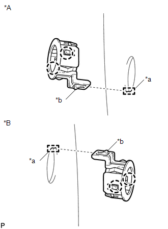
(b) Engage the clamp. Text in Illustration
|
|
.png)
(c) Connect the connector.
4. INSTALL REAR BUMPER ASSEMBLY
(See page .gif) )
)
 Removal
REMOVAL
PROCEDURE
1. REMOVE REAR BUMPER ASSEMBLY
(See page )
2. REMOVE ULTRASONIC SENSOR CLIP
(a) Disconnect the connector.
Text in Illustration
*A
...
 Brake (front)
...
Other materials about Toyota Venza:
LVL Terminal Circuit
DESCRIPTION
By connecting terminals LVL and CG of the DLC3, the headlight leveling
ECU assembly initializes the height control sensor signal.
WIRING DIAGRAM
PROCEDURE
1.
CHECK HARNESS AND CONNECTOR (DLC3 - HEADLIGH ...
Key battery
Replace the battery with a new one if it is discharged.
- You will need the following items:
• Flathead screwdriver (To prevent damage to the key, cover the tip of the screwdriver
with rag.)
• Small Phillips-head screwdriver
• Lithium battery ...
Vehicle Speed Signal Circuit between Radio Receiver and Combination Meter
DESCRIPTION
for Automatic Sound Levelizer (ASL):
This circuit is necessary for the Automatic Sound Levelizer (ASL) built
into the radio and display receiver assembly.
The Automatic Sound Levelizer (ASL) function automatically adjusts the
a ...

0.1341