Toyota Venza: Installation
INSTALLATION
PROCEDURE
1. INSTALL FRONT SHOULDER BELT ANCHOR ADJUSTER ASSEMBLY
|
(a) Engage the adjuster positioning hole with the guide and install the front shoulder belt anchor adjuster assembly with the 2 bolts. Torque: 42 N·m {428 kgf·cm, 31 ft·lbf} |
|
.png)
2. INSTALL FRONT SEAT OUTER BELT ASSEMBLY
|
(a) Engage the 2 guides. |
|
.png)
(b) Install the front seat outer belt assembly with the bolt.
Torque:
7.5 N·m {77 kgf·cm, 66 in·lbf}
|
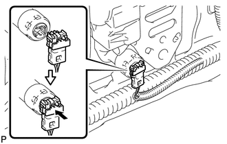
(c) Connect the connector and lock the locking button as shown in the illustration. NOTICE: Securely lock the locking button. |
|
|
(d) Connect the shoulder anchor of the front seat outer belt assembly with the nut. Torque: 42 N·m {428 kgf·cm, 31 ft·lbf} |
|
.png)
3. INSTALL UPPER CENTER PILLAR GARNISH
.gif)
4. INSTALL LOWER CENTER PILLAR GARNISH
5. CONNECT FRONT SEAT OUTER BELT ASSEMBLY
|
(a) Install the floor end of the front seat outer belt assembly with the bolt. Torque: 42 N·m {428 kgf·cm, 31 ft·lbf} |
|
.png)
(b) Check if the ELR locks.
NOTICE:
The check should be performed with the outer belt assembly installed.
(1) With the belt assembly installed, check that the belt locks when it is pulled out quickly.
6. INSTALL LAP BELT OUTER ANCHOR COVER
|
(a) Engage the 3 claws to install the lap belt outer anchor cover. |
|
.png)
7. CONNECT REAR DOOR OPENING TRIM WEATHERSTRIP
|
(a) Connect the rear door opening trim weatherstrip. |
|
.png)
8. INSTALL REAR DOOR SCUFF PLATE
9. CONNECT FRONT DOOR OPENING TRIM WEATHERSTRIP
|
(a) Connect the front door opening trim weatherstrip. |
|
.png)
10. INSTALL FRONT DOOR SCUFF PLATE
11. CONNECT CABLE TO NEGATIVE BATTERY TERMINAL
NOTICE:
When disconnecting the cable, some systems need to be initialized after the cable
is reconnected (See page ).
12. INSPECT SRS WARNING LIGHT
(a) Inspect the SRS warning light (See page
).
 Inspection
INSPECTION
PROCEDURE
1. INSPECT FRONT SEAT OUTER BELT ASSEMBLY
NOTICE:
Do not disassemble the retractor.
(a) Before installing the front seat outer belt assembly, check the ELR.
(1) When the i ...
 Disposal
DISPOSAL
CAUTION / NOTICE / HINT
CAUTION:
Before performing pre-disposal deployment of any SRS component, review and closely
follow all applicable environmental and hazardous material regulations ...
Other materials about Toyota Venza:
Rear Sensor Communication Malfunction (C1AED)
DESCRIPTION
This DTC is stored when there is an open or short circuit in the communication
line between the rear sensors and the ECU, or when there is a malfunction in a rear
sensor.
DTC No.
DTC Detection Condition
Troubl ...
Components
COMPONENTS
ILLUSTRATION
ILLUSTRATION
ILLUSTRATION
ILLUSTRATION
ILLUSTRATION
ILLUSTRATION
...
Removal
REMOVAL
PROCEDURE
1. REMOVE INSTRUMENT PANEL SAFETY PAD ASSEMBLY
(See page )
2. REMOVE NO. 1 ANTENNA CORD SUB-ASSEMBLY
(a) Disengage the 7 clamps and remove the No. 1 antenna cord sub-assembly.
3. REMOVE ROOF HEADLINING ASSEMBLY
(See page )
4. REMO ...

0.1412