Toyota Venza: Installation
INSTALLATION
PROCEDURE
1. INSTALL REAR SEAT ASSEMBLY RH
(a) Place the rear seat assembly RH in the cabin.
NOTICE:
Be careful not to damage the vehicle body.
|
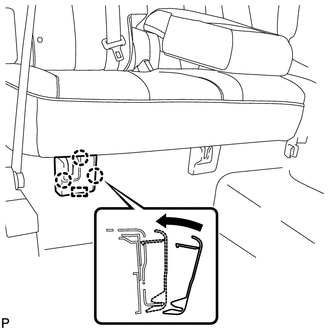
(b) Temporarily install the 2 bolts on the front side of the seat. |
|
.png)
|
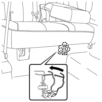
(c) Temporarily install the 3 bolts on the rear side of the seat. |
|
.png)
(d) Install the rear seat assembly RH with the 5 bolts.
Torque:
37 N·m {377 kgf·cm, 27 ft·lbf}
2. CONNECT REAR SEAT RECLINING CONTROL CABLE SUB-ASSEMBLY
(a) Connect the rear seat reclining control cable as shown in the illustration.
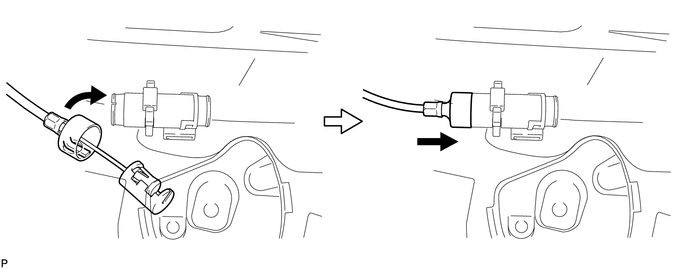
(b) Connect the rear seat reclining control cable sub-assembly as shown in the illustration.
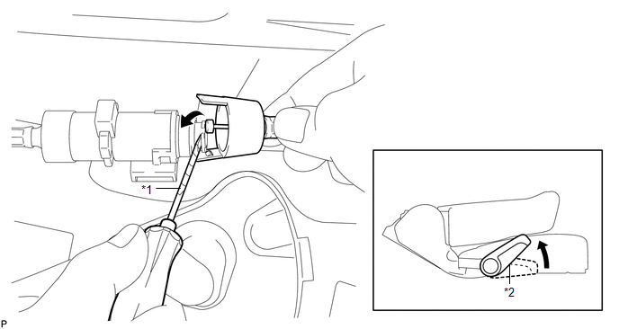 Text in Illustration
|
*1 |
Protective Tape |
*2 |
Seat Track Adjusting Handle |
|
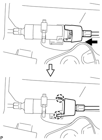
(c) Engage the 2 claws and connect the rear seat reclining control cable sub-assembly as shown in the illustration. |
|
(d) Return the seatback to the upright position.
(e) Pull up the adjuster's lock piece to lock it as shown in the illustration.
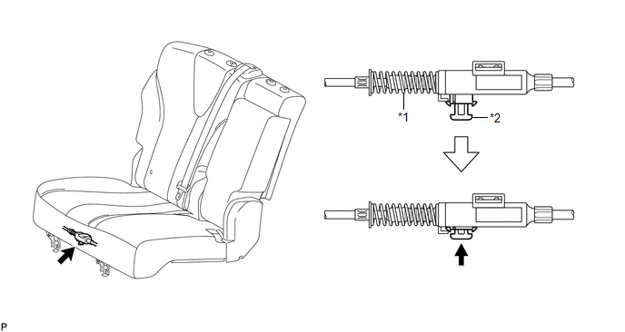 Text in Illustration
|
*1 |
Adjuster Spring |
*2 |
Lock Piece |
NOTICE:
When pressing the lock piece, make sure the adjuster's spring is not compressed.
3. INSTALL REAR SEAT OUTER TRACK BRACKET COVER
|
(a) Engage the 3 claws and guide, and install the rear seat outer track bracket cover as shown in the illustration. |
|
4. INSTALL REAR SEAT INNER TRACK BRACKET COVER
|
(a) Engage the 3 claws and guide, and install the rear seat inner track bracket cover as shown in the illustration. |
|
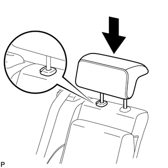
5. INSTALL REAR SEAT CENTER HEADREST ASSEMBLY
|
(a) Install the rear seat center headrest assembly as shown in the illustration. |
|
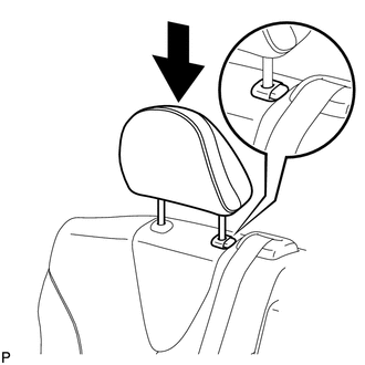
6. INSTALL REAR SEAT HEADREST ASSEMBLY
|
(a) Install the rear seat headrest assembly as shown in the illustration. |
|
 Reassembly
REASSEMBLY
PROCEDURE
1. INSTALL REAR SEAT LEG ASSEMBLY RH
(a) Using a T55 "TORX" socket wrench, install the rear seat leg assembly
RH with the 5 "TORX" bolts.
...
 Seat Heater Control
Components
COMPONENTS
ILLUSTRATION
Installation
INSTALLATION
PROCEDURE
1. INSTALL SEAT HEATER CONTROL SUB-ASSEMBLY
(a) Engage the clamp and install the seat heater control sub- ...
Other materials about Toyota Venza:
Evaporative Emission System Switching Valve Control Circuit High (P2420)
DTC SUMMARY
DTC No.
Monitoring Item
Malfunction Detection Condition
Trouble Area
Detection Timing
Detection Logic
P2420
Vent valve stuck open (vent)
Follo ...
IG Power Supply Voltage Malfunction (C1551)
DESCRIPTION
The power steering ECU distinguishes the ignition switch status as ON or off
through the IG power source circuit.
DTC No.
DTC Detection Condition
Trouble Area
C1551
IG power source ci ...
Inspection
INSPECTION
PROCEDURE
1. INSPECT TIE ROD ASSEMBLY LH
(a) Secure the tie rod assembly LH in a vise.
(b) Install the nut to the stud bolt.
(c) Flip the ball joint back and forth 5 times.
(d) Set a to ...

0.1274