Toyota Venza: Installation
INSTALLATION
PROCEDURE
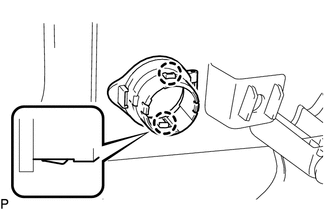
1. INSTALL REAR POWER POINT SOCKET COVER
|
(a) Engage the 2 claws to install the rear power point socket cover. |
|
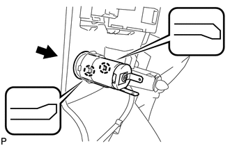
2. INSTALL REAR POWER POINT SOCKET ASSEMBLY
|
(a) Engage the 2 claws to install the rear power point socket assembly as shown in the illustration. |
|
3. INSTALL DECK TRIM SIDE PANEL ASSEMBLY RH
.gif)
4. CONNECT REAR SEAT OUTER BELT ASSEMBLY RH
HINT:
Use the same procedure for the RH side and the LH side (See page
).
5. INSTALL LUGGAGE HOLD BELT STRIKER ASSEMBLY
HINT:
Use the same procedure for the RH side and the LH side (See page
).
6. INSTALL RECLINING REMOTE CONTROL BEZEL RH
HINT:
Use the same procedure for the RH side and the LH side (See page
).
7. INSTALL REAR SEAT ASSEMBLY RH
8. CONNECT REAR SEAT RECLINING CONTROL CABLE
9. INSTALL REAR SEAT OUTER TRACK BRACKET COVER
10. INSTALL REAR SEAT INNER TRACK BRACKET COVER
11. INSTALL REAR SEAT CENTER HEADREST ASSEMBLY
12. INSTALL REAR SEAT HEADREST ASSEMBLY
13. INSTALL REAR FLOOR FINISH PLATE
14. INSTALL REAR SEAT SUB FLOOR PANEL ASSEMBLY
15. INSTALL NO. 1 DECK BOARD
16. INSTALL DECK SIDE TRIM BOX RH
17. INSTALL NO. 2 DECK BOARD SUB-ASSEMBLY
18. INSTALL DECK SIDE TRIM BOX LH
19. INSTALL NO. 3 DECK BOARD SUB-ASSEMBLY
20. INSTALL DECK BOARD ASSEMBLY
21. INSTALL TONNEAU COVER ASSEMBLY (w/ Tonneau Cover)
22. INSTALL REAR DOOR OPENING TRIM WEATHERSTRIP RH
HINT:
Use the same procedure for the RH side and the LH side (See page
).
23. INSTALL REAR DOOR SCUFF PLATE RH
HINT:
Use the same procedure for the RH side and the LH side (See page
).
 Components
COMPONENTS
ILLUSTRATION
ILLUSTRATION
ILLUSTRATION
ILLUSTRATION
...
 Removal
REMOVAL
PROCEDURE
1. REMOVE REAR DOOR SCUFF PLATE RH
HINT:
Use the same procedure for the RH side and the LH side (See page
).
2. REMOVE REAR DOOR OPENING TRIM WEATHERSTRIP RH
HINT:
Use the s ...
Other materials about Toyota Venza:
Wireless-linked Return Function does not Operate
DESCRIPTION
When the vehicle doors are unlocked through wireless unlock or entry unlock*1
operation, the certification ECU (smart key ECU assembly)*1 or main body ECU (driver
side junction block assembly) sends the key ID signal and memory call request si ...
Engine
General Maintenance
GENERAL MAINTENANCE
CAUTION / NOTICE / HINT
HINT:
Perform these procedures after the engine has cooled down.
PROCEDURE
1. INSPECT DRIVE BELT
Engine Type
See Procedure
2GR-FE
See pag ...
Removal
REMOVAL
PROCEDURE
1. REMOVE FRONT WIPER ARM HEAD CAP
(a) Using a screwdriver, remove the 2 front wiper arm head caps as shown
in the illustration.
Text in Illustration
*1
Protective Tape
...

0.1323