Toyota Venza: Installation
INSTALLATION
PROCEDURE
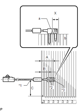
1. INSTALL NO. 1 COOLER THERMISTOR
|
(a) Install the No. 1 cooler thermistor as shown in the illustration.
NOTICE:
|
|
|||||||||||||||||||
2. INSTALL COOLER EVAPORATOR SUB-ASSEMBLY
.gif)
3. INSTALL BLOWER ASSEMBLY WITH COOLER EVAPORATOR SUB-ASSEMBLY
4. INSTALL COOLER EXPANSION VALVE
5. INSTALL AIR CONDITIONING HARNESS ASSEMBLY
6. INSTALL NO. 2 AIR DUCT SUB-ASSEMBLY
7. INSTALL NO. 3 AIR DUCT SUB-ASSEMBLY
8. INSTALL NO. 2 FINISH PANEL MOUNTING BRACKET
9. INSTALL NO. 1 FINISH PANEL MOUNTING BRACKET
10. INSTALL AIR CONDITIONING UNIT ASSEMBLY
(See page )
 Inspection
INSPECTION
PROCEDURE
1. INSPECT EVAPORATOR TEMPERATURE SENSOR
(a) Measure the resistance according to the value(s) in the table below.
Standard Resistance:
Tester Connection
...
 Refrigerant
...
Other materials about Toyota Venza:
Installation
INSTALLATION
PROCEDURE
1. INSTALL NO. 1 ULTRASONIC SENSOR RETAINER
(a) Engage the 2 claws to install the No. 1 ultrasonic sensor retainer
to the rear bumper assembly.
Text in Illustration
*A
LH Side
...
ABS Control System Malfunction (43)
DESCRIPTION
This DTC is output when the VSC system detects a malfunction in the ABS control
system.
DTC Code
DTC Detection Condition
Trouble Area
43
Malfunction in the ABS control system.
...
Sensor (Motor) Failure (B2341,B2344)
DESCRIPTION
When the sliding roof ECU (sliding roof drive gear sub-assembly) detects a motor
malfunction and the sliding roof operation is stopped, DTC B2341 is output.
When the sliding roof ECU (sliding roof drive gear sub-assembly) detects a gear
malfu ...

0.1737