Toyota Venza: Installation
INSTALLATION
PROCEDURE
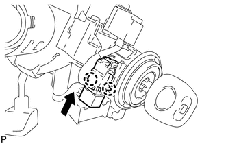
1. INSTALL UNLOCK WARNING SWITCH
|
(a) Engage the 2 claws and install the unlock warning switch to the steering column upper bracket. |
|
(b) Extract the key.
|
(c) Connect the connector. |
|
.png)
2. INSTALL TURN SIGNAL SWITCH ASSEMBLY WITH SPIRAL CABLE SUB-ASSEMBLY
.gif)
3. INSTALL UPPER STEERING COLUMN COVER
4. INSTALL LOWER STEERING COLUMN COVER
5. ALIGN FRONT WHEELS FACING STRAIGHT AHEAD
6. ADJUST SPIRAL CABLE
7. INSTALL STEERING WHEEL ASSEMBLY
8. INSTALL STEERING PAD
9. INSTALL LOWER NO. 3 STEERING WHEEL COVER
10. INSTALL LOWER NO. 2 STEERING WHEEL COVER
11. INSPECT STEERING WHEEL CENTER POINT
12. CONNECT CABLE TO NEGATIVE BATTERY TERMINAL
NOTICE:
When disconnecting the cable, some systems need to be initialized after the cable
is reconnected (See page ).
13. INSPECT STEERING PAD
14. INSPECT SRS WARNING LIGHT
(See page )
 Removal
REMOVAL
PROCEDURE
1. ALIGN FRONT WHEELS FACING STRAIGHT AHEAD
2. DISCONNECT CABLE FROM NEGATIVE BATTERY TERMINAL
CAUTION:
Wait at least 90 seconds after disconnecting the cable from the negative ...
 Wireless Door Lock Buzzer
Components
COMPONENTS
ILLUSTRATION
Installation
INSTALLATION
PROCEDURE
1. INSTALL WIRELESS DOOR LOCK BUZZER
(a) Engage the clamp and install the wireless door lock buzzer.
...
Other materials about Toyota Venza:
System Description
SYSTEM DESCRIPTION
1. GENERAL
(a) Deceleration sensors used for the airbag system are installed on various
parts on the vehicle and calculate the deceleration rate of each part during a collision.
(b) Depending on the situation, the center airbag sensor a ...
Using a flat bed truck
If you use chains or cables to tie down your vehicle, the angles shaded in black
must be 45°.
Do not overly tighten the tie downs or the vehicle may be damaged.
NOTICE
- To prevent body damage when towing a sling-type truck
Do not tow with a sli ...
Camshaft Position "B" - Timing Over-Advanced or System Performance (Bank 1)
(P0014,P0015)
DESCRIPTION
Refer to DTC P0013 (See page ).
DTC No.
DTC Detection Condition
Trouble Area
P0014
The valve timing is stuck at a certain value when in the advance range
(2 trip detection logic).
...

0.1375