Toyota Venza: Installation
INSTALLATION
PROCEDURE
1. INSTALL OUTER REAR VIEW MIRROR ASSEMBLY
|
(a) Engage the 3 claws to install the outer rear view mirror assembly as shown in the illustration. |
|
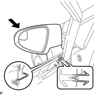
(b) Install the 3 nuts.
Torque:
8.0 N·m {82 kgf·cm, 71 in·lbf}
(c) Connect the connector.
(d) Install the hole plug.
2. INSTALL FRONT DOOR SERVICE HOLE COVER
.gif)
3. INSTALL OUTER MIRROR CONTROL ECU ASSEMBLY (w/ Memory)
4. INSTALL DOOR SIDE AIRBAG SENSOR
5. INSTALL FRONT DOOR INSIDE HANDLE SUB-ASSEMBLY
6. INSTALL FRONT DOOR TRIM BOARD SUB-ASSEMBLY
7. INSTALL COURTESY LIGHT ASSEMBLY
8. INSTALL POWER WINDOW REGULATOR MASTER SWITCH ASSEMBLY WITH FRONT DOOR ARMREST BASE PANEL (for Driver Side)
9. INSTALL POWER WINDOW REGULATOR SWITCH ASSEMBLY WITH FRONT DOOR ARMREST BASE PANEL (for Front Passenger Side)
10. INSTALL FRONT DOOR INSIDE HANDLE BEZEL PLUG
11. CONNECT CABLE TO NEGATIVE BATTERY TERMINAL
NOTICE:
When disconnecting the cable, some systems need to be initialized after the cable
is reconnected (See page ).
12. INSPECT SRS WARNING LIGHT
(See page )
 Reassembly
REASSEMBLY
PROCEDURE
1. INSTALL SIDE TURN SIGNAL LIGHT ASSEMBLY
2. INSTALL OUTER MIRROR COVER
3. INSTALL OUTER MIRROR LIGHT ASSEMBLY
4. INSTALL OUTER MIRROR
...
 Outer Rear View Mirror Cover
Components
COMPONENTS
ILLUSTRATION
Installation
INSTALLATION
PROCEDURE
1. INSTALL OUTER MIRROR COVER
(a) Engage the 7 claws to install the outer mirror cover.
...
Other materials about Toyota Venza:
Fail-safe Chart
FAIL-SAFE CHART
1. FAIL-SAFE OPERATION
If there is a problem with sensor signals or actuator systems, the skid
control ECU prohibits power supply to the brake actuator assembly and informs
the ECM of VSC system malfunction.
The brake actuat ...
Inspection
INSPECTION
PROCEDURE
1. INSPECT PARKING BRAKE SWITCH ASSEMBLY
(a) Measure the resistance according to the value(s) in the table below.
Standard Resistance:
Tester Connection
Switch Condition
...
Disassembly
DISASSEMBLY
PROCEDURE
1. REMOVE BRAKE MASTER CYLINDER RESERVOIR ASSEMBLY
(a) Mount the brake master cylinder sub-assembly in a vise.
NOTICE:
Place aluminum plates on the vise to prevent damage to the brake master cylinder
sub-assembly.
(b) U ...

0.1554