Toyota Venza: Installation
INSTALLATION
PROCEDURE
1. INSTALL TELEVISION CAMERA ASSEMBLY (w/ Rear View Monitor System)
.gif)
2. INSTALL BACK DOOR OPENER SWITCH ASSEMBLY
3. INSTALL NO. 1 BACK DOOR EMBLEM
4. INSTALL NO. 2 BACK DOOR NAME PLATE
5. INSTALL BACK DOOR OUTSIDE GARNISH SUB-ASSEMBLY
(a) Install the 5 stud bolts and 5 new gaskets to the back door outside garnish sub-assembly.
(b) Install 16 new clips (back door moulding clip) to the back door outside garnish sub-assembly.
|
(c) Engage the 16 clips to install the back door outside garnish sub-assembly. |
|
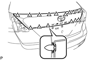
|
(d) Install the 5 nuts. |
|
(e) Connect each connector.
6. INSTALL REAR LIGHT ASSEMBLY LH
7. INSTALL REAR LIGHT ASSEMBLY RH
HINT:
Use the same procedure for the RH side and LH side.
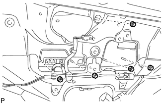
8. INSTALL REAR WIPER MOTOR AND BRACKET ASSEMBLY
9. INSTALL REAR WIPER MOTOR GROMMET
10. INSTALL REAR WIPER ARM AND BLADE ASSEMBLY
11. INSTALL REAR WIPER ARM HEAD CAP
12. INSTALL BACK DOOR PANEL TRIM ASSEMBLY
 Components
COMPONENTS
ILLUSTRATION
ILLUSTRATION
...
 Removal
REMOVAL
PROCEDURE
1. REMOVE BACK DOOR PANEL TRIM ASSEMBLY
2. REMOVE REAR WIPER ARM HEAD CAP
3. REMOVE REAR WIPER ARM AND BLADE ASSEMBLY
4. REMOVE REAR WIPER MOTOR GROMMET
5. REMOVE R ...
Other materials about Toyota Venza:
Adjusting the settings
- Adjusting the temperature setting
Turn the temperature control dial clockwise (warm) or counterclockwise (cool).
The air conditioning system switches between dual and simultaneous modes each
time is pressed.
Each temperature setting will be displ ...
Steering Angle Sensor Communication Stop Mode
DESCRIPTION
Detection Item
Symptom
Trouble Area
Steering Angle Sensor Communication Stop Mode
"Steering Angle Sensor" is not displayed on "CAN Bus Check"
screen ...
System Description
SYSTEM DESCRIPTION
1. AUTOMATIC LIGHT CONTROL SYSTEM
When the light control switch is in the AUTO position, the automatic light control
system detects ambient light levels and controls the low beam headlights, parking
lights, taillights, marker lights an ...

0.1449