Toyota Venza: Installation
INSTALLATION
PROCEDURE
1. INSTALL HOOD LOCK CONTROL CABLE ASSEMBLY
(a) Pass the hood lock control cable assembly into the engine compartment.
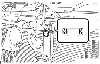
(b) Pass the cable through the upper radiator support.
(c) Engage the each clamp shown in the illustration.
2. INSTALL LOWER NO. 1 INSTRUMENT PANEL FINISH PANEL
.gif)
3. INSTALL COWL SIDE TRIM SUB-ASSEMBLY LH
4. INSTALL FRONT DOOR SCUFF PLATE LH
5. INSTALL HOOD LOCK ASSEMBLY (w/o Engine Hood Courtesy Switch)
|
(a) Apply MP grease to the sliding areas of the lock. |
|
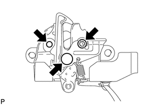
(b) Connect the hood lock control cable.
|
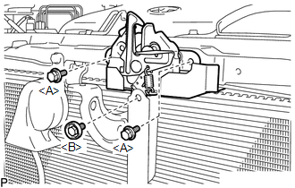
(c) Install the hood lock assembly with the 3 bolts. Torque: <A> Centering Bolt : 8.0 N·m {82 kgf·cm, 71 in·lbf} Torque: <A> Standard Bolt : 7.5 N·m {77 kgf·cm, 66 in·lbf} Torque: <B> : 8.0 N·m {82 kgf·cm, 71 in·lbf} |
|
|
(d) Install a new hood lock nut cap. |
|
6. INSTALL HOOD LOCK ASSEMBLY (w/ Engine Hood Courtesy Switch)
|
(a) Apply MP grease to the sliding areas of the lock. |
|
(b) Connect the hood lock control cable.
|
(c) Install the hood lock assembly with the 3 bolts. Torque: <A> Centering Bolt : 8.0 N·m {82 kgf·cm, 71 in·lbf} Torque: <A> Standard Bolt : 7.5 N·m {77 kgf·cm, 66 in·lbf} Torque: <B> : 8.0 N·m {82 kgf·cm, 71 in·lbf} |
|
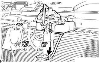
(d) Connect the connector.
|
(e) Install a new hood lock nut cap. |
|
7. INSTALL LOW PITCHED HORN ASSEMBLY
8. INSTALL RADIATOR GRILLE
9. INSTALL COOL AIR INTAKE DUCT SEAL
10. INSTALL FRONT FENDER LINER LH
(a) Install the front fender liner LH with new grommet.
(b) Install the 5 clips <A>.
(c) Install the clip <B>.
(d) Install the bolt and 6 clips.
|
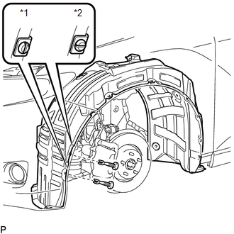
(e) Install the 2 pin hold clips. Text in Illustration
NOTICE: Insert the pin hold clip with the slot aligned vertically. Do not rotate the clip after inserting it. After installation, confirm that the slot is vertical. |
|
11. INSTALL FRONT WHEEL LH
12. INSTALL FRONT FENDER OUTSIDE MOULDING LH
13. INSPECT HOOD SUB-ASSEMBLY
14. ADJUST HOOD SUB-ASSEMBLY
 Components
COMPONENTS
ILLUSTRATION
ILLUSTRATION
...
 Removal
REMOVAL
PROCEDURE
1. REMOVE FRONT WHEEL LH
2. REMOVE FRONT FENDER OUTSIDE MOULDING LH
3. REMOVE FRONT FENDER LINER LH
(a) Using a screwdriver, turn the pin 90 degrees and remove the ...
Other materials about Toyota Venza:
Checking Monitor Status
CHECKING MONITOR STATUS
The purpose of the monitor result (mode 06) is to allow access to the results
of on-board diagnostic monitoring tests of specific components/systems that are
not continuously monitored. Examples are catalysts and evaporative emissi ...
Components
COMPONENTS
ILLUSTRATION
ILLUSTRATION
ILLUSTRATION
ILLUSTRATION
ILLUSTRATION
ILLUSTRATION
...
Removal
REMOVAL
PROCEDURE
1. REMOVE UPPER BACK WINDOW PANEL TRIM
2. REMOVE BACK DOOR PANEL TRIM ASSEMBLY
3. DISCONNECT POWER BACK DOOR ROD (w/ Power Back Door)
4. REMOVE BACK DOOR TRIM COVER LH (w/o Power Back Door)
5. REMOVE BACK DOOR TRIM COVER LH ...

0.1415