Toyota Venza: Installation
INSTALLATION
PROCEDURE
1. INSTALL FRONT SUSPENSION MEMBER BODY MOUNTING REAR CUSHION LH
|
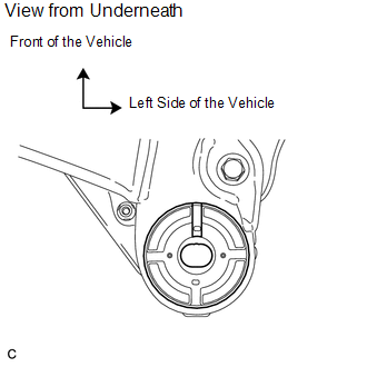
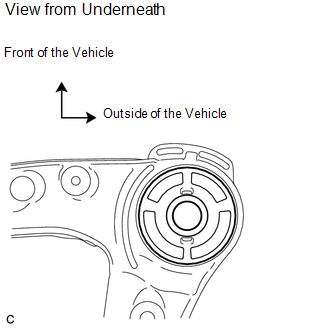
(a) Temporarily install a new front suspension member body mounting rear cushion LH while confirming the installation direction. NOTICE: Position the front suspension member body mounting rear cushion in the correct direction. |
|
|
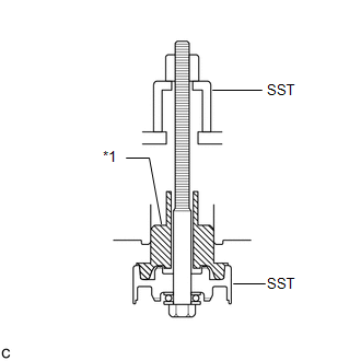
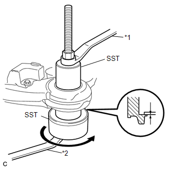
(b) Install SST as shown in the illustration. Text in Illustration
SST: 09830-10010 09830-01010 09830-01020 09830-01030 09830-01060 |
|
|
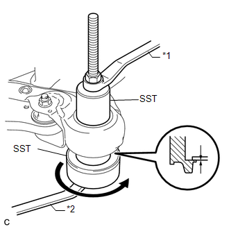
(c) Using SST, install the front suspension member body mounting rear cushion LH as shown in the illustration. Text in Illustration
NOTICE: Make sure that there is no clearance between the front suspension member and front suspension member body mounting rear cushion LH. |
|
2. INSTALL FRONT SUSPENSION MEMBER BODY MOUNTING REAR CUSHION RH
|
(a) Temporarily install a new front suspension member body mounting rear cushion RH while confirming the installation direction. NOTICE: Position the front suspension member body mounting rear cushion in the correct direction. |
|
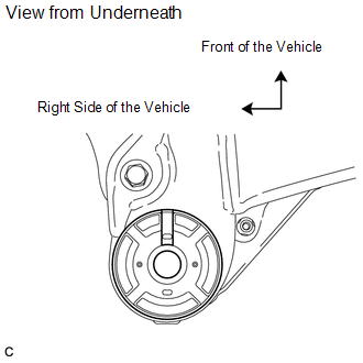
(b) Using SST, install the front suspension member body mounting rear cushion RH.
SST: 09830-10010
09830-01010
09830-01020
09830-01030
09830-01060
HINT:
Perform the same procedure as for the LH side.
3. INSTALL FRONT SUSPENSION MEMBER BODY MOUNTING FRONT CUSHION
|
(a) Temporarily install a new front suspension member body mounting front cushion while confirming the installation direction. NOTICE: Position the front suspension member body mounting front cushion in the correct direction. |
|
|
(b) Using SST, install the front suspension member body mounting front cushion as shown in the illustration. Text in Illustration
SST: 09830-10010 09830-01010 09830-01020 09830-01030 09830-01060 NOTICE: Make sure that there is no clearance between the front suspension member and front suspension member body mounting front cushion. |
|
4. INSTALL FRONT SUSPENSION MEMBER BODY MOUNTING REAR STOPPER
5. INSTALL FRONT SUSPENSION MEMBER BODY MOUNTING FRONT STOPPER
6. INSTALL FRONT SUSPENSION MEMBER DYNAMIC DAMPER (for 2WD)
|
(a) Install the front suspension member dynamic damper with the 2 bolts. Torque: 29 N·m {296 kgf·cm, 21 ft·lbf} |
|
.png)
7. INSTALL FRONT LOWER SUSPENSION ARM LH
.gif)
8. INSTALL FRONT LOWER SUSPENSION ARM RH
HINT:
Perform the same procedure as for the LH side.
9. TEMPORARILY TIGHTEN FRONT ENGINE MOUNTING INSULATOR ASSEMBLY (for 2GR-FE)
10. TEMPORARILY TIGHTEN ENGINE MOUNTING INSULATOR LH (for 2GR-FE)
11. TEMPORARILY TIGHTEN ENGINE MOUNTING INSULATOR RH (for 2GR-FE)
12. TEMPORARILY TIGHTEN REAR ENGINE MOUNTING INSULATOR ASSEMBLY (for 2GR-FE)
13. INSTALL FRONT FRAME ASSEMBLY (for 2GR-FE)
14. FULLY TIGHTEN FRONT ENGINE MOUNTING INSULATOR ASSEMBLY (for 2GR-FE)
15. FULLY TIGHTEN ENGINE MOUNTING INSULATOR LH (for 2GR-FE)
16. FULLY TIGHTEN ENGINE MOUNTING INSULATOR RH (for 2GR-FE)
17. FULLY TIGHTEN REAR ENGINE MOUNTING INSULATOR ASSEMBLY (for 2GR-FE)
18. TEMPORARILY TIGHTEN FRONT ENGINE MOUNTING INSULATOR ASSEMBLY (for 1AR-FE)
19. TEMPORARILY TIGHTEN ENGINE MOUNTING INSULATOR LH (for 1AR-FE)
20. TEMPORARILY TIGHTEN ENGINE MOUNTING INSULATOR RH (for 1AR-FE)
21. TEMPORARILY TIGHTEN REAR ENGINE MOUNTING INSULATOR ASSEMBLY (for 1AR-FE AWD)
22. INSTALL FRONT FRAME ASSEMBLY (for 1AR-FE)
23. INSTALL REAR ENGINE MOUNTING INSULATOR ASSEMBLY (for 1AR-FE AWD)
24. FULLY TIGHTEN FRONT ENGINE MOUNTING INSULATOR ASSEMBLY (for 1AR-FE)
25. FULLY TIGHTEN ENGINE MOUNTING INSULATOR LH (for 1AR-FE)
26. FULLY TIGHTEN ENGINE MOUNTING INSULATOR RH (for 1AR-FE)
27. FULLY TIGHTEN REAR ENGINE MOUNTING INSULATOR ASSEMBLY (for 1AR-FE AWD)
28. INSTALL STEERING LINK ASSEMBLY
29. INSTALL FRONT STABILIZER BAR WITH FRONT STABILIZER LINK ASSEMBLY
30. INSTALL FRONT NO. 1 STABILIZER BRACKET LH
31. INSTALL FRONT NO. 1 STABILIZER BRACKET RH
HINT:
Perform the same procedure as for the LH side.
32. INSTALL ENGINE ASSEMBLY WITH TRANSAXLE (for 2GR-FE)
HINT:
Refer to the procedure from Install Engine Assembly with Transaxle (See page
).
33. INSTALL ENGINE ASSEMBLY WITH TRANSAXLE (for 1AR-FE)
HINT:
Refer to the procedure from Install Engine Assembly with Transaxle (See page
).
 Removal
REMOVAL
PROCEDURE
1. REMOVE ENGINE ASSEMBLY WITH TRANSAXLE (for 2GR-FE)
HINT:
Refer to the procedure up to Remove Engine Assembly with Transaxle (See page
).
2. REMOVE ENGINE ASSEMBLY WITH TRAN ...

Other materials about Toyota Venza:
Brake Switch "B" Circuit High (P0724)
DESCRIPTION
The purpose of this circuit is to prevent the engine from stalling when the brakes
are suddenly applied while driving in the lock-up condition.
When the brake pedal is depressed, this switch sends a signal to the TCM. Then
the TCM cancels the ...
Installation
INSTALLATION
PROCEDURE
1. INSTALL OUTER MIRROR SWITCH
(a) Engage the 4 claws to install the outer mirror switch.
2. INSTALL OUTER MIRROR SWITCH ASSEMBLY
(a) Engage the 2 claws to install ...
Precaution
PRECAUTION
NOTICE:
When disconnecting the cable from the negative (-) battery terminal, initialize
the following systems after the cable is reconnected.
System Name
See Procedure
Back Door Closer System
...

0.1761